Summary of 48×8 SCROLLING MATRIX LED DISPLAY USING ARDUINO CONTROLLER
This project demonstrates a scrolling text display on a 48×8 monochrome LED dot matrix using an Arduino Uno. The system utilizes six 74HC595 shift registers to drive columns and one for rows, controlled by transistors and specific Arduino pins. A custom C++ sketch manages bitmap data for alphabets and implements right-to-left scrolling logic with adjustable speed via delay loops.
Parts used in the 48x8 Scrolling Matrix LED Display:
- Arduino Uno microcontroller
- 48×8 LED dot matrix display
- Six 74HC595 shift registers for columns
- One 74HC595 shift register for rows
- Transistors for column driving
- Resistors (implied for current limiting)
- Wiring and breadboard components
- Arduino Software environment
A monochrome (single colour) LED dot matrix display is used for displaying the Characters and Symbols which is interface with a microcontroller. This project will deliberate on displaying a scrolling text message on a 48×8 LED dot matrix display. The microcontroller used is Arduino Uno which is open source prototype Electronic platform. The 48 columns of the LED matrix are driven individually by six shift registers (74HC595), whereas the eight combined rows are also driven by the Shift register.
Here we will be scanning across the rows and feed the column lines with appropriate logic levels. The program in the microcontroller is to determine the speed of the scrolling message as well as Message what we are going to display. The technique will be demonstrated for right to left scroll, but can be easily implemented for scrolling in other directions. The Sketch program for Arduino Uno is developed with Arduino Software.
Step 1: PREPARING THE MATRIX
Matrix wiring each matrix has 64 LEDs. Instead the LEDs are wired into a matrix. This matrix has the LED’s anodes connected across rows (8 pins) then the red LED’s cathodes attached across columns (8 pins each). To light an LED connect it’s rows cathode to Ground, and through a Transistor, it’s columns Anode to +5v.
Displaying Images (Scanning) Now that we can light any LED we choose it’s time to move on to displaying a (small) image. To do this we will use a scan pattern. In the example code we define a bitmap image (an array of 8 bytes, each bit representing one LED). Next we scan through this array one byte at a time, displaying one column then the next. If we do this fast enough (about 1000 times a second) it appears as an image. It sounds complex but if you download the code and play around it should quickly become clear
Step 2: CONNECTING THE SHFIT REGISTERS AND TRANSISTORS.
Here we use 74HC595 to drive the row and colum
single shift register to drive the row
and daisy chained shift registers with common clock pin to drive columns
– Each shift register can drive 8 columns
-Based on the number of columns number of shift registers can be increased,there is no limit for the columns.
Step 3: Interfacing with Arduino
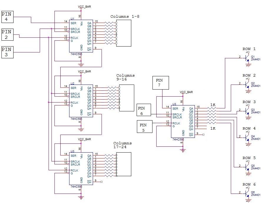
Pin of Arduino Shift register pins
5 – 12
6 – 11
7 – 14
the above are for the column drivers
9 – 12
10 – 11
8 – 14
the above are for the row drivers
Step 4: PROGRAM
int x;
int y;
int latchPin1 = 5; //Arduino pin connected to blue 12 RCLK of 74HC595
int clockPin1 = 6; //Arduino pin connected to green 11 SRCLK of 74HC595
int dataPin1 = 7; //Arduino pin connected to violet 14 SER of 74HC595
//– Rows (Positive Anodes) —
int latchPin2 = 9; //Arduino pin connected to yellow Latch 12 RCLK of 74HC595
int clockPin2 = 10; //Arduino pin connected to white Clock 11 SRCLK of 74HC595
int dataPin2 = 8; //Arduino pin connected to grey Data 14 SER of 74HC595
//=== B I T M A P ===
//Bits in this array represents one LED of the matrix
// 8 is # of rows, 7 is # of LED matrix we have
byte bitmap[8][7]; // Change the 7 to however many matrices you want to use.
int numZones = sizeof(bitmap) / 8;
int maxZoneIndex = numZones-1;
int numCols = numZones * 8;
byte alphabets[][5] = {
{0,0,0,0,0},
{31, 36, 68, 36, 31},
{127, 73, 73, 73, 54},
{62, 65, 65, 65, 34},
{127, 65, 65, 34, 28},
{127, 73, 73, 65, 65},
{127, 72, 72, 72, 64},
{62, 65, 65, 69, 38},
{127, 8, 8, 8, 127},
{0, 65, 127, 65, 0},
{2, 1, 1, 1, 126},
{127, 8, 20, 34, 65},
{127, 1, 1, 1, 1},
{127, 32, 16, 32, 127},
{127, 32, 16, 8, 127},
{62, 65, 65, 65, 62},
{127, 72, 72, 72, 48},
{62, 65, 69, 66, 61},
{127, 72, 76, 74, 49},
{50, 73, 73, 73, 38},
{64, 64, 127, 64, 64},
{126, 1, 1, 1, 126},
{124, 2, 1, 2, 124},
{126, 1, 6, 1, 126},
{99, 20, 8, 20, 99},
{96, 16, 15, 16, 96},
{67, 69, 73, 81, 97},
};
//=== S E T U P ===
void setup() {
pinMode(latchPin1, OUTPUT);
pinMode(clockPin1, OUTPUT);
pinMode(dataPin1, OUTPUT);
pinMode(latchPin2, OUTPUT);
pinMode(clockPin2, OUTPUT);
pinMode(dataPin2, OUTPUT);
//– Clear bitmap —
for (int row = 0; row > 8; row++) {
for (int zone = 0; zone <= maxZoneIndex; zone++) {
bitmap[row][zone] = 0;
}
}
}
//=== F U N C T I O N S ===
// This routine takes whatever we’ve setup in the bitmap array and display it on the matrix
void RefreshDisplay()
{
for (int row = 0; row < 8; row++) {
int rowbit = 1 << row;
digitalWrite(latchPin2, LOW); //Hold latchPin LOW for as long as we’re transmitting data
shiftOut(dataPin2, clockPin2, MSBFIRST, rowbit); //Transmit data
//– Start sending column bytes —
digitalWrite(latchPin1, LOW); //Hold latchPin LOW for as long as we’re transmitting data
//– Shift out to each matrix (zone is 8 columns represented by one matrix)
for (int zone = maxZoneIndex; zone >= 0; zone–) {
shiftOut(dataPin1, clockPin1, MSBFIRST, bitmap[row][zone]);
}
//– Done sending Column bytes, flip both latches at once to eliminate flicker
digitalWrite(latchPin1, HIGH
digitalWrite(latchPin2, HIGH
//– Wait a little bit to let humans see what we’ve pushed out onto the matrix —
delayMicroseconds(500);
}
}
// Converts row and colum to actual bitmap bit and turn it off/on
void Plot(int col, int row, bool isOn)
{
int zone = col / 8;
int colBitIndex = x % 8;
byte colBit = 1 << colBitIndex;
if (isOn)
bitmap[row][zone] = bitmap[y][zone] | colBit;
else
bitmap[row][zone] = bitmap[y][zone] & (~colBit);
}
// Plot each character of the message one column at a time, updated the display, shift bitmap left.
void AlphabetSoup()
{
char msg[] = “YOUR TEXT “;
for (int charIndex=0; charIndex < (sizeof(msg)-1); charIndex++)
{
int alphabetIndex = msg[charIndex] – ‘@’;
if (alphabetIndex < 0) alphabetIndex=0;
//– Draw one character of the message —
for (int col = 0; col < 6; col++)
{
for (int row = 0; row < 8; row++)
{
bool isOn = 0;
if (col<5) isOn = bitRead( alphabets[alphabetIndex][col], 7-row ) == 1;
Plot( numCols-1, row, isOn
}
//– The more times you repeat this loop, the slower we would scroll —
for (int refreshCount=0; refreshCount < 7; refreshCount++) //change this value to vary speed
RefreshDisplay();
//– Shift the bitmap one column to left —
for (int row=0; row<8; row++)
{
for (int zone=0; zone < numZones; zone++)
{
bitmap[row][zone] = bitmap[row][zone] >> 1;
// Roll over lowest bit from the next zone as highest bit of this zone.
if (zone < maxZoneIndex) bitWrite(bitmap[row][zone], 7,
bitRead(bitmap[row][zone+1],0));
}
}
}
}
}
//=== L O O P ===
void loop() {
AlphabetSoup();
}
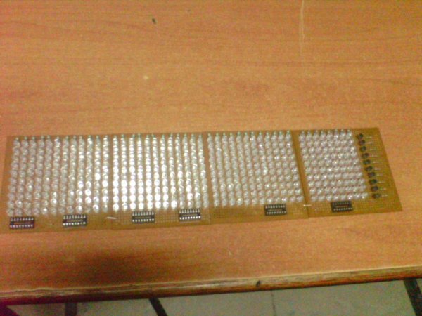
Step 5: OUTPUT OF MY BUILD
THE OUTPUT OF MY BUILD 8X48 MATRIX SCROLL DISPLAY
Source: 48×8 SCROLLING MATRIX LED DISPLAY USING ARDUINO CONTROLLER
- What microcontroller is used in this project?
The Arduino Uno open source prototype electronic platform is used. - How are the 48 columns of the LED matrix driven?
The columns are driven individually by six daisy chained 74HC595 shift registers. - Can the scrolling direction be changed from right to left?
Yes, the technique demonstrated for right to left scroll can be easily implemented for other directions. - What determines the speed of the scrolling message?
The program determines the speed based on the number of times the refresh loop is repeated within the code. - How many LEDs are in each individual matrix unit mentioned?
Each matrix unit has 64 LEDs wired into an 8x8 configuration. - Which Arduino pins connect to the column driver shift register?
Pins 5, 6, and 7 connect to the latch, clock, and data pins respectively for the column drivers. - How does the scanning technique make the image visible?
Scanning through the array about 1000 times a second makes the sequential lighting appear as a static image. - What is the function of the transistor in the circuit?
The transistor connects the column anode to +5v when the row cathode is connected to Ground to light an LED.