Summary of Xyluino – an Arduino Driven MIDI Marimba, Xylophone, Glockenspiel
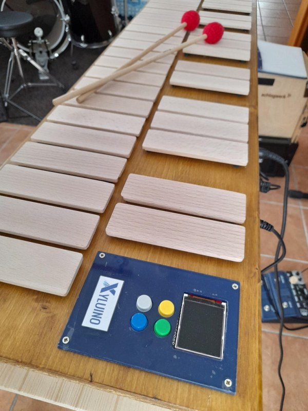
This article details the construction of the Xyluino, an Arduino-driven MIDI marimba/xylophone. The project utilizes 42 bleech wood plates with piezo sensors to generate three and a half octaves of sound. Three analog multiplexers manage the sensor inputs for the Arduino Uno, which processes signals via custom code to send MIDI commands without external libraries. The system includes controls for instrument changes, octave shifting, and sustain pedals, allowing users to trigger sounds on a separate processor like the Ketron SD4.
Parts used in the Xyluino:
- Arduino Uno Rev. 3
- Analog multiplexer (74HC4067)
- Piezo sensors (approx. 3cm diameter)
- Bleech wood plates
- Epoxy glue
- Sponge rubber parts
- Electronic components (wires, buttons, display, midi socket)
- Sustain pedal input
Supplies
What you need:
- an arduino, I use an arduino Uno, Rev. 3
- analog multiplexer, 74HC4067
- piezos, diameter about 3cm
- wood, bleech wood for the plates
- knowledge how to solder
- some electronic parts, wires, buttons, a display, midi socket
Step 1: Collect Information, Test the Basics
This step is just for your information and not really necessary. There are many sources on the internet concerning arduino, midi, piezo sensors, drum kits and so on. Here are mine:
MIDI Drum Kit:
https://todbot.com/arduino/sketches/midi_drum_kit…
E-Drum Set:
http://blog.georgmill.de/2011/03/22/e-drumset-selb…
Drumkit:
https://www.spikenzielabs.com/learn/drumkitkit.htm…
I really found a small xylophone made of plastic and some basic code:
Arduino xylophone:
https://jdeboi.com/projects/2011/xylophone.html
and source code:
https://github.com/jdeboi/xylophone/blob/master/ne…
And for arduino and midi:
MIDI tutorial:
https://learn.sparkfun.com/tutorials/midi-tutoria…
MIDI and arduino:
https://fortyseveneffects.github.io/arduino_midi_l…
https://newt.phys.unsw.edu.au/jw/notes.html
http://www.philrees.co.uk/articles/midimode.htm
https://www.youtube.com/playlist?list=PL4_gPbvyeb…
https://www.instructables.com/id/Send-and-Receive-…
At the end I do not use any kind of midi library. There is too much overhead in the code just for sending some small commands from the device which I can program with a line of code and the serial interface.
A big challenge was the speed of the arduino. Will it be sufficient polling three and a half octave of piezo sensors in time? Yes, it is. I have tuned the analogue input a little bit for speeding it up and everything is fine.
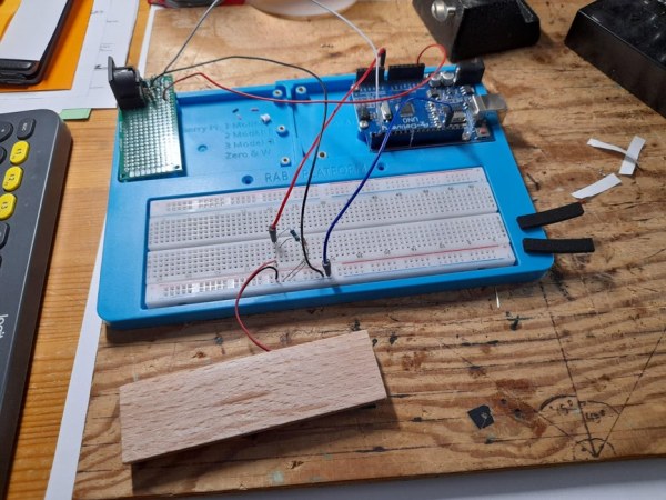
The technical principle of this instrument are some piezo sensors, some analog multiplexers and analog inputs of the arduino.The tuning of the sensors is done by software. You can control sensitivity and delay of every input. I will go into details with the program code later on.
On the photo you see my first setup of one sensor generating one midi note on a breadboard.
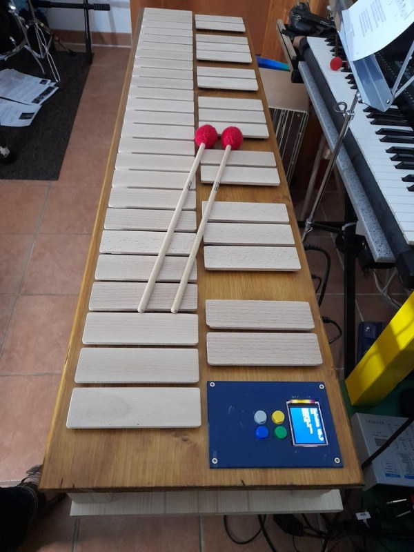
Step 2: The Sensor Part
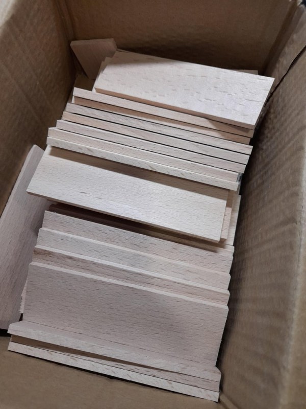
The input sensors are made of bleech wood. It’s a hard wood, so you are able playing it with different kind of sticks later on. I’ve glued the piezo plates with an epoxy glue at the bottom of the bleech wood plates. For reducing transmissions of vibrations between the sensors I put some small parts of sponge rubber on the plates.
Now I’ve done that 42 times for having three and a half octaves of tones at the end.
Step 3: Analog Multiplexer
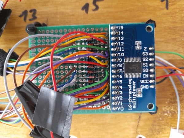
For collecting the analogue signal I’m using analog multiplexers connected to the analogue inputs of the arduino. One multiplexer can collect 16 channels. For 42 sensors I used three of them. There’s a lot of repeating work to do. Be careful with the wiring. Label the sensors otherwise you will end up with a chaos of cables.
Step 4: The Main Electronics
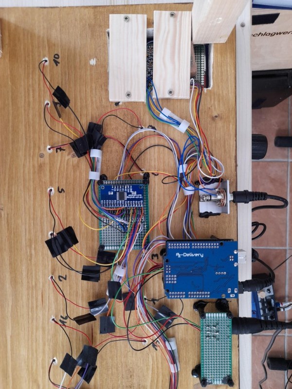
The last step is wiring it all together. The analogue multiplexers, the arduino, a display, some buttons, midi buttons and an input for a sustain pedal.
Step 5: The Circuit Diagram
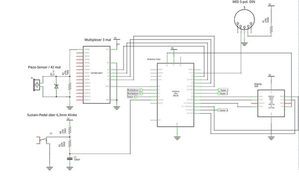
Here is the circuit diagram (the descriptions are in German – sorry for that). You need the multiplexer three times and the sensor hardware 42 times. The buttons for controlling the instrument are set up like the electronic for the sustain pedal, there is no difference.
Step 6: The Program
Let’s go deeper into the programming code.
The main program is devided in subroutines.
// midiLoopback();
This is not used yet, but could be added if some midi loopback is needed. Therefore you have to add an optocoupler and a midi-in socket.
readSensors();
This routine reads all sensors over the multiplex arrays. The routines reads the three input signals at once and stores it in the array.
checkSensors();
This is for analyzing the values read before. If a sensor was hit, the program waits a small amount of time before analyzing the signal again. This is for reducing oscillations. The routine sets the duration for playing a midi note and dependig of the octave value set the appropriate note read from the array of notes.
A dynamic attack is possible to set. But for me it was not very useful. Therefore I’ve deactivated it.
checkPedal();
This is for analyzing the sustain pedal. The routine is independent from playing a note.
InstrumentChange();
As mentioned above, I am using a Ketron SD4 for generating sounds from the midi controls. I’ve stored some instruments in the user bank of the device which I loop with a program change midi control. Using another kind of sound processor you have to customize these lines of code.
checkOctave();
The octave button is checked and loops MID-LOW-MID-HIGH-MID-… With this function the maximum octave range is five and a half octaves.
Let’s explain some subroutines.
This routine is for making the analogg readings faster
// Making analog readings faster (for drumrolls) works with this code
// read http://www.arduino.cc/cgi-bin/yabb2/YaBB.pl?num=1… for more info #define FASTADC 1
// defines for setting and clearing register bits
#ifndef cbi
#define cbi(sfr, bit) (_SFR_BYTE(sfr) &= ~_BV(bit))
#endif
#ifndef sbi
#define sbi(sfr, bit) (_SFR_BYTE(sfr) |= _BV(bit))
#endif
#if FASTADC
// set prescale to 16
sbi(ADCSRA,ADPS2) ;
cbi(ADCSRA,ADPS1) ;
cbi(ADCSRA,ADPS0) ;
#endif
The values of the notes being played over midi, the sensitivity and the cooldown time of the piezo sensors can be defined individually for every sensor. I’ve set these equal for all sensors. If you want you can do a lot of fine tuning.
// Midi-Notenwerte
unsigned char PadNote[72] = {36,37,38,39,40,41,42,43,44,45,46,47,48,49,50,51,52,53,54,55,
56,57,58,59,60,61,62,63,64,65,66,67,68,69,70,71,72,73,74,75,76,77,78,79,80,81,82,83,84,85,
86,87,88,89,90,91,92,93,94,95,96,97,98,99,100,101,102,103,104,105,106,107};
// Threshold Werte, Anschlagsempfindlichkeit
// Tuning-Bedarf ! Ch 10
int PadCutOff[48] = {300,300,300,300,300,300,300,300,300,300,300,300,300,300,300,300,300,
300,300,300,300,300,300,300,300,300,300,300,300,300,300,300,300,300,300,300,300,300,300,
300,300,300,300,300,300,300,300,300};
// time each note remains on after being hit
int MaxPlayTime[48] = {50,50,50,50,50,50,50,50,50,50,50,50,50,50,50,50,50,50,50,
50,50,50,50,50,50,50,50,50,50,50,50,50,50,50,50,50,50,50,50,50,50,50,50,50,50,50,50,50};
// array of flags of pad currently playing
boolean activePad[48] = {0,0,0,0,0,0,0,0,0,0,0,0,0,0,0,
0,0,0,0,0,0,0,0,0,0,0,0,0,0,0,0,0,0,0,0,0,0,0,0,0,0,0,0,0,0,0,0,0};
// counter since pad started to play
int PinPlayTime[48] = {0,0,0,0,0,0,0,0,0,0,0,0,0,0,0,0,0,0,
0,0,0,0,0,0,0,0,0,0,0,0,0,0,0,0,0,0,0,0,0,0,0,0,0,0,0,0,0,0};
The MIDI controls are in the last part of the code. The transmiaaion rate is set to 31.250 Baud.
//*******************************************************************************************************************
// Transmit MIDI Message //*******************************************************************************************************************
void MIDI_TX(unsigned char MESSAGE, unsigned char PITCH, unsigned char VELOCITY)
{ status = MESSAGE + midichannel;
Serial.write(status);
Serial.write(PITCH);
Serial.write(VELOCITY);
}
// MIDI Program Change
void MIDI_PC(unsigned char PROGRAMNUMBER)
{ status = 192 + midichannel;
Serial.write(status);
Serial.write(PROGRAMNUMBER);
}
// MIDI Control Change
void MIDI_CC(unsigned char State)
{ status = 176 + midichannel;
Serial.write(status);
Serial.write(64);
Serial.write(State);
}
Source: Xyluino – an Arduino Driven MIDI Marimba, Xylophone, Glockenspiel
- What is the main microcontroller used in this project?
The project uses an Arduino Uno, specifically Rev. 3. - How many analog multiplexers are required for the sensors?
Three multiplexers are needed because each handles 16 channels for a total of 42 sensors. - Does the author use a MIDI library for the code?
No, the author does not use any kind of MIDI library to reduce code overhead. - What material is used for the xylophone plates?
Bleech wood is used for the plates as it is a hard wood suitable for playing with sticks. - How is vibration transmission between sensors reduced?
Small parts of sponge rubber are placed on the plates to reduce vibration transmission. - What is the baud rate set for MIDI transmission in the code?
The transmission rate is set to 31.250 Baud. - Can the user change the instrument sound generated by the device?
Yes, the code loops through instruments stored in the user bank of a connected sound processor like the Ketron SD4. - What is the maximum octave range achievable with the octave button?
The maximum octave range is five and a half octaves. - How does the software handle sensor sensitivity?
The tuning of sensors is done by software where sensitivity and delay can be controlled for every input.