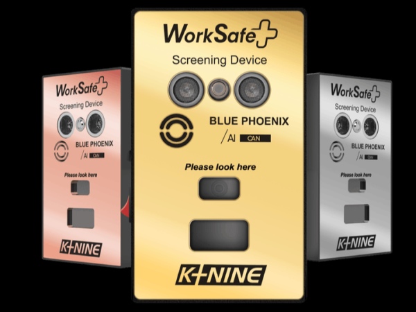
Worksafe is an attempt to bring advanced healthcare diagnostics to residential and industrial markets at affordable costs.
Description
As we all are aware, it’s been almost two years since the SARS-COV2 outbreak began in December, 2019. Initially, it put tremendous pressure on all countries to find out methods for identifying the infection. The most prominent methods of detecting the virus included chemical methods like RT-PCR, which were time-consuming and labor-intensive. Other faster and more automated methods like detection using AI and Deep Learning models based on X-Rays, CT-Scans and thermal imaging modalities were being explored, but they were still at nascent stages and not ready for mass adoption and deployment. The testing infrastructure could not keep up with the infections and this made a market for a variety of screening devices – devices like temperature guns and pulse oximeters that could measure a few vital parameters affected by the coronavirus.
Problems
Unfortunately, these devices were riddled with problems –
- They were extremely short-ranged which resulted in a lot of manual measurement errors as it is quite natural for the user to be cautious about the distance between the gun and the subject’s forehead to avoid any possibility of contracting the virus.
- The accuracy of spot IR devices has always been a concern due to the ample factors affecting them, including but not limited to relative humidity, Ambient temperature and emissivity.
- The introduction of indistinguishable cheap quality sensors to increase profit margins per device made these devices notorious and speculative among many users and researchers.
Solution – Theory
Design rules: I identified this problem in June, 2020 and started developing a device with the following design goals in mind:
- It should have at least 50 cm range.
- It should be capable of measuring more than just one or two vital parameters so that the screening is much more robust to external factors.
- It should be affordable
- It should be able to record all the data it measures with timestamps in a usable format (like .csv)
- It should have applicability beyond the pandemic
The biggest problem was the range and measuring multiple parameters. Measurement of core body temperature was done using IR technology which had a range of only a few cms. Pulse oximeters require touch to measure SPO2 and HR levels. Both these technologies were supposed to be inherently different, but actually they are not. Both make use of IR technologies of similar wavelengths.
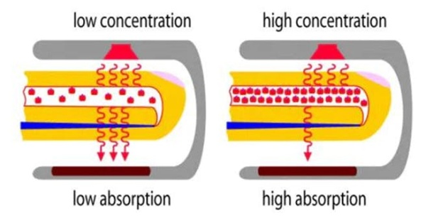
Remote-PhotoPlethysmography (r-PPG): I researched the net and came across 2 ways to address these problems. I came across something called “remote-PhotoPlethysmography” or r-PPG which caught my mind. Pulse oximeters use Photoplethysmography or PPG which basically measures how much light from the source is absorbed by the finger’s biological components. Since light is more strongly absorbed by blood than the surrounding tissues, the changes in blood flow can be detected by PPG sensors as changes in the intensity of light. The voltage signal from PPG is proportional to the quantity of blood flowing through the blood vessels which is called the PPG signal. The absorption is also affected by the SPO2 levels in the blood. Hence pulse oximeters can measure SPO2 and HR from the PPG signal. However, for this to work there has to be an IR emitter kept very close to the finger because of which pulse oximeters are contact-based.
PG is a novel take to this concept. It states that because sunlight contains all wavelengths, it also contains IR rays and acts as the source needed for measuring absorption. It uses a camera (generally visible) to measure the fluctuations in the form of skin colour variations. Yes, you heard right. Measuring SPO2 from your forehead or face. This could be the solution I am looking for!
HRV and HR calculations: PPG waveforms can also provide HRV or heart rate variability. This is another vital parameter that provides you with additional information about your heartbeats. Basically, it tells you how much each heartbeat time interval differs from the average. Normally, it is assumed that all heartbeats are different which is why you get an almost instantaneous result on the pulse oximeter. Like in ECG, PPG waveforms also have peaks that are used to calculate the RR interval.
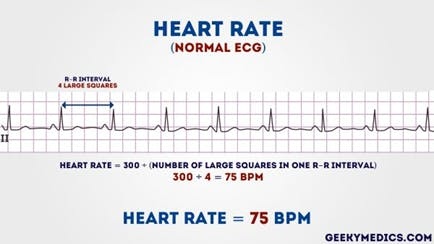
Traditional HR calculation
HR= 60/(RR interval)
However, this is not true. Each RR interval is different and might be an indication of some diseases like Atrial fibrillation or Arrhythmia. In that case,
HRV = HR/60 – RR interval
For the sake of simplicity, we still calculate the HR as mentioned above, but now we also calculate how much the current beat is different from that average. If the HRV fluctuates a lot during idling, it might an indication of some disorder. Instead, if it fluctuates while exercises, it is an indication that your body is adept and responsive. Athletes have high HRV.
Calculating SPO2, HR, HRV from r-PPG signals: As mentioned here, HR and HRV is calculated by averaging out and separating all the different colour channels of the facial skin. There are very few papers that show the calculations for spo2 measurement using r-PPG, this is one of the papers that we referred to: Non-Contact Physiological Parameters Extraction Using Facial Video Considering Illumination, Motion, Movement and Vibration.
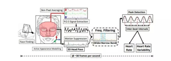
rPPG Algorithm (courtesy: https://www.noldus.com/blog/what-is-rppg)
Measuring Respiratory Rate, Respiratory Rate Variability and Core Body Temperature from 50 cm: We know that IR technology is extremely dependant on the distance between the IR sensor or thermal camera and the object emitting the IR rays or the subject. We researched and developed a few algorithms that could compensate for this drop in temperature due to distance and ambient temperature. We have published our findings on IEEE Xplore here: Enhanced Pyrometric device with Long Range for mass screening based on MLX90614. This paper received the best paper award at the International conference where we presented it in India.
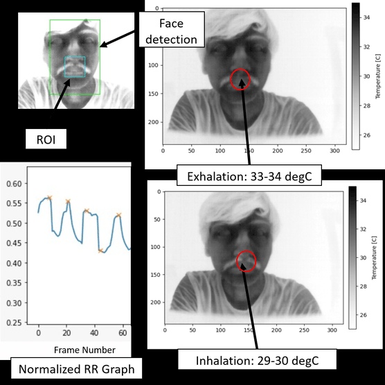
RRV is analogous to HRV conceptually. So now, we have ways to estimate most of the important parameters using long-range methods. Everything looks fine on paper, but lets move on next to the practical implementation of this.
Solution – Prototyping
We could find a lot of papers and preliminary ideation on the previously discussed concepts but we were not able to find any code or practical implementations for these concepts. We also realized that doing everything together would require an array of NIR, LWIR and visible cameras which would make our system quite costly. Hence we finalized on measuring 3 parameters first – HR (Heart Rate), SPO2 (Saturated Oxygen) and CBT (Core Body Temperature). This was because HR and SPO2 could be measured using r-PPG and a visible imaging camera, while CBT could be measured with a pyrometric sensor which is much cheaper and easily available than a thermal camera.
BOM:
We used the following main components:
- NodeMCU Lolin: To run our regression model built on MATLAB that compensates the measured object temperature for variations due to ambient temperature and distance.
- ESP32 Cam: To take video in VGA format and transmit it wirelessly over WiFi to a central server or Desktop.
- Ultrasonic Sensor SR04: To measure the distance between the pyrometric sensor and the subject
- Pyrometric sensor MLX90614: To measure the object and ambient temperature using IR technology
- 0.96″ OLED Display: For displaying warnings, temperature values and other indications
- Piezo Buzzer: For Audio Alerts
- Wall Adapter or Battery: We calculated that the power requirement for our system was around 5V 1A or 5W. Hence we provided a barrel jack on the PCB so that the device could be powered using any option as needed. More on this in the Power Budget Section.
Our BOM cost amounted to less than 2581 INR or around 35$ per pc including individual component costs, taxes as well as manufacturing for the battery variant. The CSV for the BOM is attached in the attachments, the picture below shows a gist of it. (Qtty assumed: 100 pcs). If the battery is replaced by a 5V 2A Barrel jack wall adapter, the price drops even further to about 32$ as shown below.
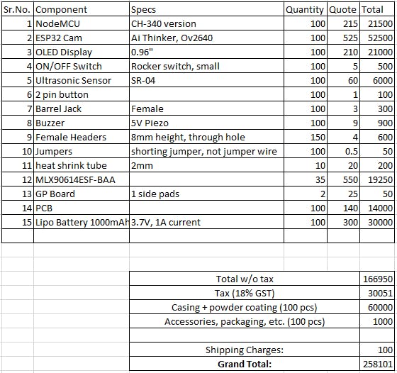
1 / 2 • BOM for 100 Pcs (Battery Variant): BOM Cost around 258101/100 = 2581 INR or 35$
This was a great price point for a product that could measure 3 vital parameters. Certified temperature guns and pulse oximeters easily cost around 50-100$ each. Hence we moved to the designing phase.
Power Budget:
The main power is consumed by the ESP32 Cam. It consumes around 180 mA if the Flash LED is off. All these values are taken from the datasheets or reference documentation of the corresponding component.
- ESP32 Cam: 180 mA
- Node MCU: 40 mA
- SR04: 15 mA
- MLX90614: 1.5 mA
- Buzzer: 10-15mA (intermittent, not continuous)
- OLED and the remaining components: A few mA
Hence, the total current consumed is around 250 mA, which should make sure that a 1000 mAh battery lasts for around 3-4 hours of continuous usage.
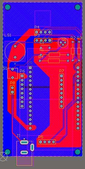
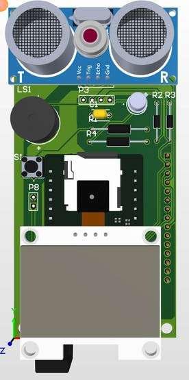
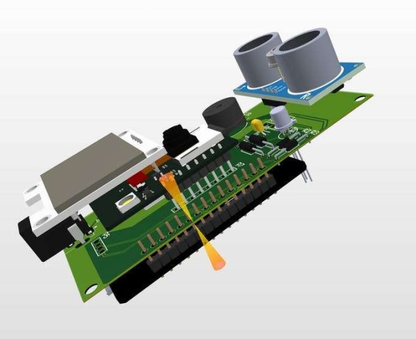
Design:
I developed my design on Altium Designer (AD20). The schematic, PCB Layout and 3D design are attached below:
The main connections are as follows:
- Node MCU D1 – SCL (Display and MLX)
- Node MCU D2 – SDA (Display and MLX)
- Node MCU D3 – ECHO (SR04 sensor)
- Node MCU D4 – GPIO12 of ESP32 Cam (wake_up GPIO)
- Node MCU D5 – Base of transistor that triggers the buzzer
- Node MCU D6 – TRIGGER (SR04 sensor)
- Node MCU D7 – Wifi AP Button (use it to change saved wifi credentials)
While the schematic is made for a supply voltage of 5V, The entire circuitry can run on either 3V with minor modifications.
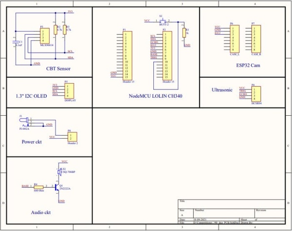
Schematic
The first Layout and design iteration:
Simple tests on the assembled PCB:
This was the first design I developed. After assembly it looked pretty well:
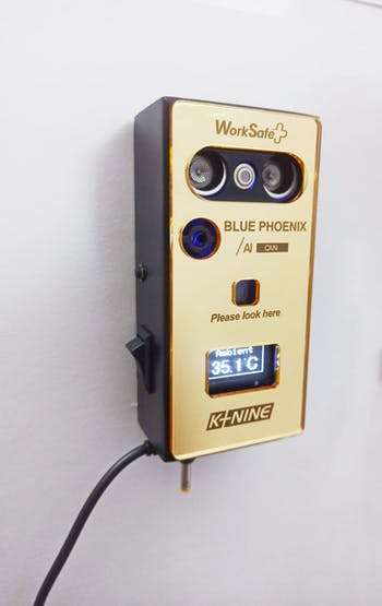
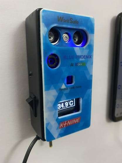
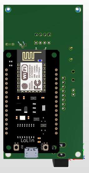
Later, I made some revisions to the PCB and the case:
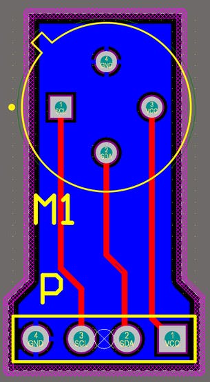
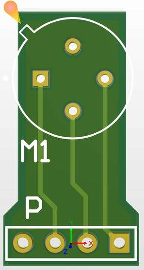
- First I developed a special PCB for the MLX sensors I was using, which helped me save a lot of costs because the modules were significantly more costly.
- Second, I noticed that I was using only one row of the Node MCU. Hence, using some quick tricks, I was able to design the board in such a way that despite overlapping, I could easily solder both the micro controllers.
- I also adjusted the location of the ESP32 cam so that its camera could be in the centre.
Source: WorkSafe CV based multiparameter monitoring and diagnostics