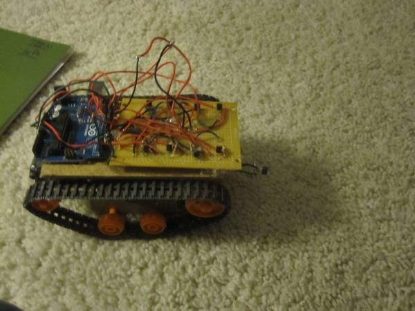
This is my first arduino robot, and I am quite happy with the outcome. What I came up with is a robot that with modifications can do just about anything in the realm of small arduino robots. The electronics are very simple. You only need an H bridge, and a simple setup for the sensor that you are using (in this case the QRD-1114 infrared reflective sensor). The chassis is also very simple. implementing the track and wheel set from Tamiya (this worked quite well with the homemade chassis), and is made from materials that are cheap, and easy to come by. If you follow this instructable, you should end up with a small robot that is capable of being configured to avoid obstacles, follow lines, and stay on a table top using the arduino microcontroller.
If you like the instructable, please vote for it in the arduino challenge.
Step 1: Materials
This robot can be configured in many different ways, so the materials you will need may vary. Here is a list of parts that I ended up using.
for the chassis:
-two pieces of peg board about 6cm by 13.5 cm
-assortment of scrap wood
-Tamiya track and wheel set (get from amazon)
-screws
for electronics:
-8x 2222A NPN transistors (you can avoid the use of transistors with the use of H bridge ICs such as the 298)
-8x 1k resistors
-perfboard
-wire
-QRD-1114
-10k resistor
-68ohm resistor
-type M male power jack
-Tamiya twin motor and gear box
software:
-arduino uno (any other arduino board should work)
Step 2: Building the chassis
I made the chassis based on the universal plate sold by Tamiya. basically you need a piece of pegboard big thin enough that there is enough of the shaft coming out from the side of your gearbox that the tracks won’t get caught on the board, that is long enough that you can fit all of your hardware on it. I started by cutting a piece of pegboard about 6 cm wide (the measurement you need if using the twin motor and gear box from tamiya) by 13 cm long. I then put two pieces of wood measuring 7cm by 1.5 cm by1.5 cm on the bottom of the pegboard with equal space on either end of the wood. I then attached two thin pieces of wood to the top of the pegboard on the front of the robot. I drilled a hole on equal distances on both pieces of wood to hold the front axle of the track and wheels. I attached two smaller wheels to the bottom pieces of wood using the partially threaded screws included in the track and wheel set
Step 3: Motors and gearbox
I used the twin motor and gear box from tamiya. I am not going to explain construction, because if you buy it there is instructions included. Be sure that you assemble it as the c type or the low speed type. The c type has a gear ratio of 203:1 as opposed to the a and b types which have a gear ratio of 58:1. The c type is the only one with enough torque for our purposes. If you are using a different gear box, assemble it with the highest gear ratio you can. when attaching to the chassis, line up the shafts with the end of the chassis, and screw it on.
note: One of the motors the gear box came with did not work. it would begin to stain and move very slowly after moving for a few minutes. I replaced it with a geared motor I got from radio shack for much better results.
Step 4: Building the H bridge.
To control the motors, you need a setup called an h bridge. You probably know that when you connect the terminals on the motors to the reversed end of the battery, it turns in the opposite direction. using switches you can switch the polarity of each terminal of the motor, and change the direction. To allow the arduino to make the switches, you need to use an electronic switch. In this case, we will use transistors, but you can also use relays, or even better, a H bridge IC chip. You will need four transistors for each motor. one transistor for each polarity on both terminals. What I did, is I connected two transistor bases together, for each direction the motor would spin, and that would be connected to the output pins on the arduino. I found that for the negative connection, you had to connect the emitter of the NPN transistor to ground, and then the collector the the terminal of the motor, and for the positive connection, you had to connect the collector to power, and the emitter to the motor terminal.
Note: the transistors I used had an Ic max of about 500 ma. The transistors got very hot unless I connected the base of the transistor to the arduino through a 1k resistor. If you choose to make a H bridge with transistors you may want to get a transistor with a higher current tolerance, or maybe even power transistors.

Step 5: Mounting the electronics
to mount the electronics, I screwed another small piece of pegboard to the pieces of would used to hold the front axle. I hot glued the H bridge down, and velcroed the arduino so I could remove it easily for use in other projects.
Step 6: Setup the sensor
To get it to work with the arduino, you need to setup the QRD in a specific way. If you saw my instructable on servos, you will setup the qrd in the same way. just follow the schematic.
For more detail: The Versatile Arduino Robot