
Summary of Using Push Button Switch with Arduino Uno
This tutorial explains how to read a digital pin's status on an Arduino Uno using a push button and an LED. It details configuring pins as INPUT, OUTPUT, or INPUT_PULLUP, emphasizing the use of internal or external pull-up resistors to prevent undefined states. The project demonstrates turning an LED on for three seconds when a switch is pressed, utilizing specific resistor values for current limiting and pull-up functionality.
Parts used in Arduino Digital Pin Status Reading:
- Arduino Uno
- Push button switch
- LED
- 10KΩ resistor (External PULL-UP)
- 680Ω resistor (Current limiting)
- Digital Pin 4
- Digital Pin 8
In this tutorial you will learn how to read the status of a digital pin of Arduino. I hope that you already go through our first tutorial, Getting Started with Arduino Uno – LED Blinking. In this example, a push button switch and an LED is connected to Arduino Uno. When we press the switch, LED will glow for 3 seconds. A pin is configured as Input Pin to connect switch and another pin is configured as Output Pin to connect LED. You need to connect PULL-UP or PULL-DOWN resistors while interfacing switch.
If we haven’t use PULL-UP or PULL-DOWN resistors, there will be an UNDETERMINED STATE (neither LOW nor HIGH) when the switch is OPEN. In this tutorial we will follow PULL-UP resistors.
Digital Pins of Arduino can be configured as OUTPUT, INPUT or INPUT_PULLUP mode using pinMode() function. INPUT_PULLUP mode is used to enable the Internal PULL-UP Resistor. The value of Internal PULL-UP resistor of Arduino Uno is about 20-50KΩ.
Now we have two options to interface switches with Arduino :
- Using External PULL-UP Resistor
- Using Internal PULL-UP Resistor
The simple solution is to using Internal PULL-UP resistor but in some cases you may have to use External PULL-UP resistors.
Using External PULL-UP Resistor
This method is not recommended, but it is explained first just because it is easy to understand. In some cases you may forced to use External PULL-UP resistor.
Circuit Diagram
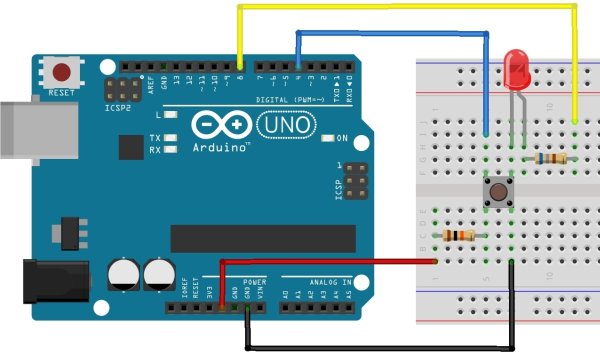
Here the switch is connected to digital pin 4 (D4) and LED is connected to digital pin 8 (D8) of Arduino Uno. Thus pin D4 should be declared as INPUT and pin D8 as OUTPUT in the sketch (program). 10KΩ resistor is used as PULL-UP resistor and a 680Ω resistor is used to limit the current through the LED.
Arduino Sketch
const int switchPin = 4; //Switch Connected to PIN 4
const int ledPin = 8; //LED Connected to PIN 8
int switchState = 0; // Variable for reading Switch status
void setup()
{
    pinMode(ledPin, OUTPUT); //LED PIN is Output
    pinMode(switchPin, INPUT);//Switch PIN is input with PULLUP
}
void loop()
{
    switchState = digitalRead(switchPin); //Reads the status of the switch.
    if (switchState == LOW) //If the switch is pressed
    {
        digitalWrite(ledPin, HIGH); //LED ON
        delay(3000); //3 Second Delay
        digitalWrite(ledPin, LOW); //LED OFF
    }
}
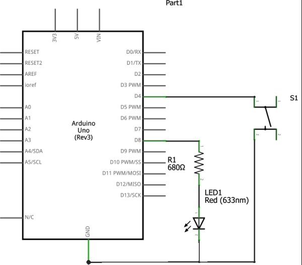
When the switch is off, pin D4 will be LOGIC HIGH state due to the action of PULL-UP resistor. Whenever the switch is pressed, pin D4 will switch to LOGIC LOW state since the closed switch will ground the pin. In the above sketch setup() funtion will run initially and sets pin modes. Then the loop() function will run as an infinite loop, which checks the status of the switch continuously. Whenever the switch press is detected, LED is turned ON and it is turned OFF after a 3 seconds delay.
For more detail: Using Push Button Switch with Arduino Uno
-
What happens if pull-up or pull-down resistors are not used?
An UNDETERMINED STATE occurs where the signal is neither LOW nor HIGH when the switch is open. -
How do you enable the Internal PULL-UP Resistor?
Configure the pin mode as INPUT_PULLUP using the pinMode function. -
What is the resistance value of the Internal PULL-UP Resistor on Arduino Uno?
The value is approximately 20-50KΩ. -
Which pins are used for the switch and LED in the example circuit?
The switch connects to digital pin 4 and the LED connects to digital pin 8. -
What logic state does pin D4 have when the switch is off?
Pin D4 remains in a LOGIC HIGH state due to the action of the PULL-UP resistor. -
What logic state does pin D4 switch to when the switch is pressed?
The pin switches to LOGIC LOW because the closed switch grounds the pin. -
How long does the LED glow after the switch is pressed?
The LED glows for 3 seconds before turning off.
