Summary of Using I2C SSD1306 OLED Display With Arduino
This tutorial explains how to use a small 0.96-inch I2C OLED display with an Arduino using just two wires for communication, simplifying the connection process. The OLED module, driven by the SSD1306 IC, features a 128x64 pixel resolution and operates between 3.3V and 6V, requiring less than 10 mA current. The display uses I2C protocol, which only needs two data lines (SCL and SDA), making it efficient for short-distance communication with the Arduino. The tutorial includes a simple wiring setup and demonstrates compatibility with Arduino Mega.
Parts used in the I2C OLED Display with Arduino Project:
- 0.96 Inch I2C OLED Display Module (SSD1306)
- Arduino Mega
- Power Source (Powerbank, Battery, or USB cable)
- Connecting Wires
Introduction
Sometimes it may be necessary to use a display when making a hardware project, but one confusing thing is the size of the display and the required pins to control it. This tutorial will show you how to use a small I2C OLED display with Arduino using only two wires.

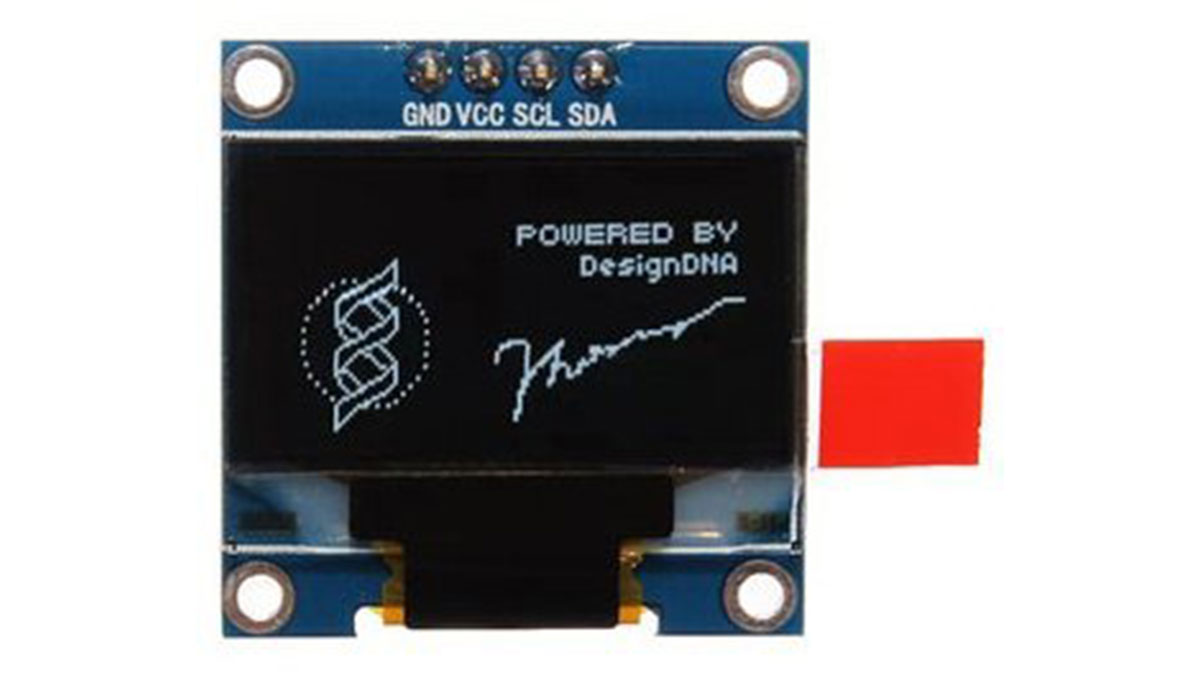
Geekcreit 0.96 Inch I2C OLED Display Module
The display used in this tutorial has a very small (2.7 x 2.8cm) OLED screen, that is similar to Arduino Pro Mini size, with 128 x 64 screen resolution. The OLED Driver IC is SSD1306, a single-chip CMOS OLED/PLED driver with controller for organic / polymer light emitting diode dot-matrix graphic display system. The module has only 4 pins, two of them are the supply pins, while the others are SCL and SDA, I2C protocol pins, which will be used to control the display.
This OLED display module is full compatible with Arduino and has an input voltage range between 3.3V and 6V and it need less than 10 mA current, so it can be connected with 3.3V or 5V pins. It is available on Banggood store for about $5.5.
Parts you will need:
- The OLED Display
- An Arduino, (Arduino Mega in this tutorial)
- Power source, Powerbank, Battery, or USB cable.
- Wires.
The Circuit
The circuit is very simple. First, connect the GND with Arduino GND, VCC with 3.3V or 5V on Arduino, SCL with SCL, and finally SDA with SDA pin. Upload the code and power on the Arduino.
I2C Protocol
The Inter-integrated Circuit (I2C) Protocol is a protocol intended to allow multiple slave digital integrated circuits to communicate with one or more master chips. It is only intended for short distance communications within a single device, and it only requires two signal wires to exchange information.
Read more: Using I2C SSD1306 OLED Display With Arduino
