
Summary of Using an Arduino to Control an Infrared Helicopter
This Instructable explains how infrared (IR) remotes encode commands as carrier-modulated digital pulses, how to capture those signals with a logic analyzer, decode their timing into binary codes, and build a simple Arduino-driven IR transmitter circuit to reproduce commands (example: Puzzlebox Orbit helicopter). It includes component values, wiring, and notes on polarity and sampling.
Parts used in the Puzzlebox Orbit IR control project:
- IR LED (IR333C/H0/L10)
- NPN transistor (2N3904)
- 47 Ohm resistor (approximate for 50 Ohm)
- 4.7k Ohm resistor (approximate for 5k)
- Arduino Uno (microcontroller)
- Logic analyzer (for capturing IR signal)
- Connecting wires, soldering or breadboard
In this Instructable we will explain how infrared signals are used by a remote to control a toy or device, then show how a simple circuit can be added to an Arduino to operate the same device through free, Open Source software.
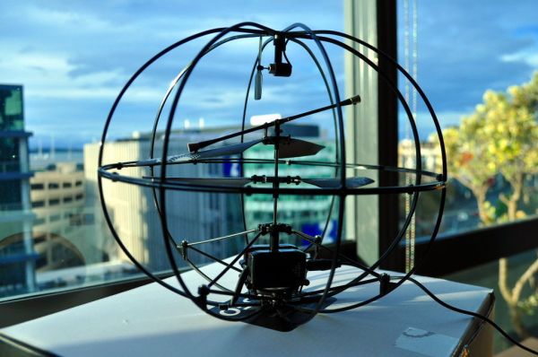
This document is part of a series covering the Puzzlebox Orbit, a brain-controlled helicopter that features an open design, open hardware, and open software. The helicopter can be operated via an EEG headset plus either a mobile device or the dedicated Puzzlebox Pyramid remote control unit. The Puzzlebox Pyramid includes a micro-controller based on the Arduino.
While we refer to the Puzzlebox Orbit in our examples, the principles, source code, and to a large extent software are all directly applicable to most any toy or devices which use infrared (IR) for remote control.
Step 1: The Remote Control
Here we explain in a very broad sense how an infrared remote control works.
There is at least 1 infrared LED (or Infrared Emitter, IR LED, IR Emitter) inside every infrared remote control, including the one you use to control your TV set. When you press a button on the remote, the IR LED will give out a certain series of “LOW”s and “HIGH”s which represents a series of “0”s and “1”s. (To be strict, it is common that a “HIGH” and a corresponding “LOW” consist of a “0”, and another combination of “HIGH” and “LOW” with different period represents a “1”.) Different series of “0”s and “1”s can mean different things, for example maybe “1100100000111” can mean “Turn Off the TV”, and “001101011100” can mean “Volume Down”.
Infrared is also cast by light and heat sources all around you: light bulbs, sunlight, heaters, even people. Therefore the remote control needs to have a distinct method of sending out infrared code to the receiving device (TV set, helicopter, car, etc.). That’s why infrared normally transmits with “carrier” – a high frequency square wave sequence (normally 36kHz, 38kHz and 40kHz). So, if you were to capture and zoom in on an infrared signal, you would find each “HIGH” consists of a sequence ofsquare waves rather than a continuous “HIGH” voltage level.
Check out Wikipedia:Infrared Remote Control for more information about infrared remote controls.
Step 2: Capturing the Control Signal
You might have a question: How can you learn the IR code used by a remote control?
One way is to use a Logic Analyzer.
A logic analyzer is an electronic instrument which displays signals in a digital circuit. (Digital circuits represent signals by discrete bands of analog levels, rather than by a continuous range. Basically if there’s only two different voltage level in a circuit, say 5V and 0V, then it’s a digital circuit. If the voltage in the circuit can be any voltage in between, then it is a analog circuit.)
Since we already know that an IR code is a digital signal rather than an analog signal, we can use a logic analyzer to capture and record the code emitted by the IR LED. First clip in to the Common(some times marked as GND, meaning “ground“) Cathode pin of the IR LED, and then clip a signal channel of the analyzer in to the Anode pin of the same IR LED. Then tell the Logic Analyzer to start recording the signal. If you don’t know which sampling rate to use, then use the highest option available.
It’s easy to identify IR LED’s polarity is simple even after they were soldered: There are two electrodes inside an IR LED, the bigger/longer one is Cathode, and the smaller one is Anode. See photo.
NOTE: It should be mentioned that if the logic analyzer fails to read an IR signal, but the controller is able to make the helicopter fly, it is possible that the test leads are clipped on the wrong way around, and that the ground and signal leads should be switched.
Step 3: Understanding how IR commands are represented by binary codes
Here we explain how the raw control signal was decoded such that an algorithm could be written to reproduce it.
Take a look at Picture 1. You can see the IR LED is sending out IR commands almost every 0.1 seconds.
Take a look at Picture 2, and pay attention to the timestamps and compare it to Picture 1. Load the A_H3RMFM.logicdata file (in the .zip file) with Saleae Logic software, move the signal data to 4s, zoom in, and you’ll see the exact same data as shown in the image.
Let’s give the combination of one “HIGH” and one “LOW” a name, say a “bit“. Then the first two bits inPicture 2 is different from the rest with HIGH=0.768ms, LOW=0.477ms, so Iet’s put them aside, because it is very possible that these two bits are specially timed to denote the start of an IR command. (Actually if you look at other commands, they always lead by these two bits.)
Then let’s look at the rest. There are only two kinds of bits left, one is HIGH=0.715ms, LOW=0.759ms, another is HIGH =0.377ms, LOW=0.422ms. let’s call the first kind of bit “7”, the second kind of bit “4”. Then the code shown in Picture 2 is 4 4 7 4 7 7 4 7 7 7 4 7 4 4 7 7 4 4 7 4 4 7 7 7 7 7 4 7 7 4 7. We can re-assign 7 to be “1” and 4 to be “0” (or the other way round). If we do so then this command equals 0010110111010011001001111101101.
 A_H3RMFM.csv2 MB
 A_H3RMFM.logicdata.zip146 KB
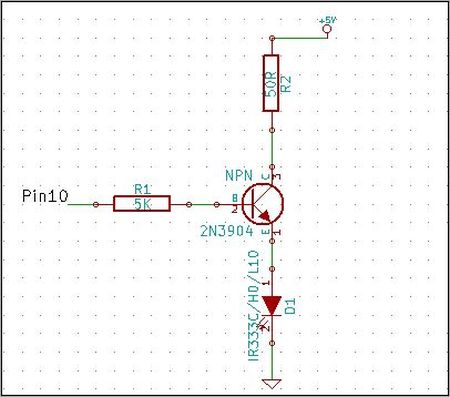
There are 4 components in the circuit 2 resistors (4.7k, 47 OHM) , 1 IR LED (IR333C/H0/L10), and 1 NPN transistor (2N3904).
- Resistors are not direction specific, both ends are the same.
- IR LED symbol, pin 1 is Anode (longer lead), pin2 is Cathode(shorter lead).
- 2N3904 is the NPN transistor. Looking at the flat face, the left lead is Emitter (pin 1 in schematic), the middle lead is Base (pin 2 in schematic), the right lead is Collector (pin 3 in schematic).
Solder components (or use a breadboard) as shown in the schematic:
- 47 Ohm resistor to Collector on NPN transistor
- 4.7K resistor to Base on NPN transistor
- Anode of IR LED (longer lead) to Emitter NPN transistor
- Another end of 50 Ohm resistor to +5v pin on Arduino. (An alternative would be use a bigger resistor, say 100 Ohm, to replace the 50 Ohm one, and connect the other end to Vin Pin on Arduino.) This resistor is to make sure we won’t burn the IR LED. The IR LED can only accept a maximum of 100 mA current, so if we use 5V to drive the IR LED, we need to make sure the current running through the LED is limited to less than 100 mA, which yields the resistance R=5V/100mA=50 Ohm. The nearest commonly-found resistor is 47 Ohm.
- Another end of 5K Ohm resistor to Pin 10 on Arduino Uno. The nearest commonly-found resistor is 4.7k Ohm.
- Cathode of IR LED (shorter lead) to GND on Arduino Uno.
For more detail: Using an Arduino to Control an Infrared Helicopter
- How does an infrared remote represent commands?
Commands are encoded as sequences of HIGH and LOW pulses (bits) where each HIGH usually contains a carrier square wave; different timing patterns represent different bits and full codes. - How can you capture the IR code from a remote?
Use a logic analyzer: clip ground to the IR LED common/cathode and a signal channel to the IR LED anode, then record at the highest sampling rate available. - Can ambient infrared interfere with remote signals?
Yes; light bulbs, sunlight, heaters and other sources emit infrared, so remotes use a carrier frequency (commonly 36–40 kHz) to distinguish signals. - What components are required to add an IR transmitter to an Arduino?
The circuit uses an IR LED, a 2N3904 NPN transistor, a ~47 Ohm current-limiting resistor, and a ~4.7k resistor for the transistor base, plus an Arduino and wiring. - How is the IR LED connected in the transistor circuit?
The IR LED anode (longer lead) goes to the transistor emitter; the IR LED cathode (shorter lead) goes to Arduino GND; the transistor collector connects through the 47 Ohm resistor to +5V. - What Arduino pin is used to drive the IR transistor base?
Pin 10 on the Arduino Uno is used, connected to the transistor base via the 4.7k resistor. - Why is a 47 Ohm resistor used with the IR LED?
The resistor limits current so the IR LED receives less than its 100 mA maximum; using 5V requires about 50 Ohm, so 47 Ohm is used as the nearest common value. - How do you identify IR LED polarity after soldering?
The longer/bigger internal electrode is the anode and the shorter is the cathode.
