
Summary of Unipolar 4-Phase Stepper Motor Controller
This project is a 4-phase unipolar stepper motor controller board designed to drive stepper motors or solenoids. It utilizes Darlington transistors for high current capacity and includes diodes to protect against back EMF. A high-wattage resistor on the board allows users to adjust current limits based on load requirements. The board features IDC connectors, screw terminals, LED indicators for phases and power, and four mounting holes for easy installation.
Parts used in the Unipolar 4-Phase Stepper Motor Controller:
- Darlington transistors
- Diodes
- High Watt resistor
- IDC connector (Box Header)
- Screw terminal connector
- Individual Phase LED indicators
- Power-On LED indicator
- PCB board (86 mm x 49 mm)
- Mounting holes (3.2 mm)
C055_1
This project is a 4-phase unipolar stepper motor controller.
Description
Unipolar 4-Phase Stepper Motor Controller Board will help you control a Stepper Motor or 4 individual Solenoids. This circuit consisting of transistors that serve as current amplifier and also diode to prevent damaging back EMF, circuit uses Darlington transistors to provide high current capacity to unipolar stepper motor. Just provide sequence of pulse using Micro-Controller or descript circuit to roll out the unipolar motor. On board High Watt resistor to control the current, value of the resistor can be set as per your load current requirement.
Specifications
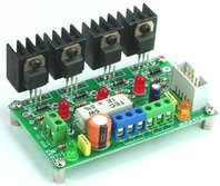
Box Header (IDC) connector provides for easy interfacing option
Separate LED indicator for individual Phase
Screw terminal connector for easy connection of output load and power supply input
Power-On LED indicator
Four mounting holes of 3.2 mm each
PCB dimensions 86 mm x 49 mm
For More Details: Unipolar 4-Phase Stepper Motor Controller
-
What is the primary function of this circuit?
The circuit controls a Stepper Motor or 4 individual Solenoids using a 4-phase unipolar configuration. -
How does the circuit prevent damage from back EMF?
It uses diodes within the circuit to prevent damaging back EMF. -
Which components provide high current capacity?
Darlington transistors are used to serve as current amplifiers providing high current capacity. -
Can the current limit be adjusted?
Yes, the value of the onboard High Watt resistor can be set according to your load current requirement. -
How do I control the motor sequence?
You must provide a sequence of pulses using a Micro-Controller or a dedicated circuit. -
What type of connectors are included for interfacing?
The board features a Box Header (IDC) connector for easy interfacing and screw terminal connectors for output load and power supply input. -
Are there visual indicators on the board?
Yes, there are separate LED indicators for individual phases and a Power-On LED indicator. -
What are the dimensions of the PCB?
The PCB dimensions are 86 mm x 49 mm.
