
Summary of Ultrasonic Range Finder
This article details building a non-contact range finder using an Arduino Uno R3 and an HC-SR04 ultrasonic module. The project measures distances between 2cm and 400cm with +/- 3mm accuracy, utilizing a simple four-wire connection and custom code to calculate distance based on sound wave return times.
Parts used in the Non-Contact Range Finder:
- HC-SR04 ultrasonic module
- Arduino Uno R3
- Male-female jumper wires
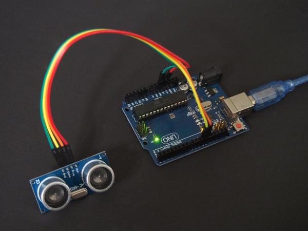
This instructable describes how to create a non-contact range-finder using an Arduino and an HC-SR04 ultrasonic module to measure distances in the range 2cm – 400cm.
The accuracy is typically +/- 3mm depending on distance, air temperature, and humidity.
Step 1: Parts List
Very few parts are required:
- 1 only HC-SR04 ultrasonic module or similar
- 1 only Arduino Uno R3
- 4 only Arduino male-female jumper wires
All items were obtained from https://www.aliexpress.com/
Step 2: Wiring Diagram
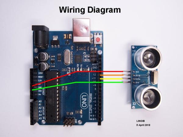
Only four wires are required to complete this project.
The wiring diagram is shown in photo1.
Step 3: Theory
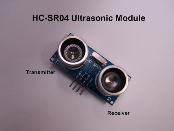
The HC-SR04 ultrasonic range-finder module (photo 1) provides non-contact measurements in the range 2cm – 400cm. The accuracy is typically +/- 3mm depending on distance, air temperature, and humidity.
For greatest accuracy the target area should be at least 0.5 square meters. Best results are obtained when the transducer is pointing directly at the target. Useable results, however, are possible within an imaginary “cone” of +/- 15 degrees.
Interfacing the HC-SR04 to an Arduino is extremely simple as, apart from the two supply pins, only two wires, “Trig” (trigger) and “Echo”, are required.
A 10uS (microsecond) trigger pulse must be applied to the “Trig” pin to start each measurement.
On receipt of a trigger pulse the module emits an eight cycle “burst” at a frequency of 40kHz (kilohertz) after which the “Echo” line goes HIGH. There is a short 430uS interval between the trigger pulse and the rising edge of the “Echo” pin during which time high energy +/-10 volt charges are built up in the transmitter circuit prior to the ultrasonic burst.
The “Echo” pin drops LOW on receipt of an echo signal or 210mS whichever comes first.
[ Note:
If you block the ultrasonic signals (I used a rolled up sock against the transducers), you will observe a distance reading of 3550cm which is outside the sensor range of approximately 400cm.
Beyond 400cm the distance readings will suddenly jump to 3550cm. The reason for this follows:
In normal operation the measure() function completes its measurement in less than 25mS (423cm) then waits a further 25mS until the task scheduler next sets TaskFlag1 “TRUE”.
Should an echo not be received, the task scheduler will continue to set TaskFlag1 “TRUE” every 50mS until the HC-SR04 times out after 210mS and the Echo pin drops low. All 10uS start pulses generated by the measure() function during this time are ignored by the HC-SR04.
The timeout value of 210mS corresponds to a distance of 3550cm … hence the sudden jump in the distance reading.
The important point is that all distance readings less than 400cm are correct. ]
Typical waveforms
Waveforms for 5cm, 10cm, 20cm, and 200cm distances are shown in photos 2,3,4, and 5.
The top trace in each photo is the “Trig” pin … the lower trace in each photo is the “Echo” pin.
The duration of each “Echo” pulse can be calculated by multiplying the trace length by the “uS/div” value shown in the lower-right corner of each photo.
Calculating the distance
The exact distance can be calculated from the formula:
- distance (cm) = pulse-length * speed-of-sound / 2 * 100 ………………………………….. (1)
This assumes that the “speed-of-sound” is 340m/S, and that the echo-distance is twice the actual distance.
The distance can also be calculated using the formula:
- distance (cm) = pulse-length (uS) / 59 ………………………………………………………………….. (2)
The exact distance can be obtained by adjusting the constant value of 59.
[ Note:
The value of 59 for the constant is derived as follows:
The speed of sound is approximately 340m/S which is 0.034cm/uS (centimeters/microsceond).
The reciprocal of 0.034cm/uS is 29.412uS/cm which, when multiplied by 2 to allow for the return path, equals 58.824 or 59 when rounded. ]
Example 1:
Substituting a pulse-length of 2400uS into equation (1) we get:
- distance = 2400/1000000 * 340/2 * 100 = 40.8cm
Example 2:
Substituting a pulse-length of 2400uS into equation (2) we get:
- distance = 2400/59 = 40.7cm
Step 4: The Code
The code comprises a “measure()” function that is called once every 50mS using the task-scheduler described in instructable https://www.instructables.com/id/Multi-task-Your-…
The measure() function comprises the following code:
// ----- generate 10uS start pulse
digitalWrite(Trig,HIGH);
delayMicroseconds(10);
digitalWrite(Trig,LOW);

// ----- measure the distance
while (!digitalRead(Echo));   	//wait for Echo pin to go high
start_time =  micros();
while (digitalRead(Echo));  	//wait for Echo pin to go low
finish_time = micros();
time_taken = finish_time - start_time;
Distance = ((float)time_taken)/59;
The complete code, “Ultrasonic_range_finder.ino”, is attached.
Copy the contents of this text file to an Arduino sketch, save it as “Ultrasonic_range_finder” (without the quotes), then compile and upload it to your Arduino.
Step 5: Measuring Distances
To view the distance readings click “Tools|Serial Monitor” and set the speed to 115200 bauds.
The distance readings may be calibrated by placing an object along a ruler then adjusting the constant “59” value for “Distance” until an exact reading is displayed.
Click here to view my other instructables.
Source: Ultrasonic Range Finder
- What is the measurement range of this device?
The device measures distances in the range of 2cm to 400cm. - How accurate is the distance measurement?
The accuracy is typically +/- 3mm depending on distance, air temperature, and humidity. - Can I use this sensor at angles other than directly facing the target?
Yes, usable results are possible within an imaginary cone of +/- 15 degrees from the transducer. - Does the sensor require many wires for connection?
No, only four wires are required including two supply pins, Trig, and Echo. - What happens if no echo is received by the sensor?
The reading suddenly jumps to 3550cm after the 210mS timeout period expires. - How can I calibrate the distance readings?
You can adjust the constant value of 59 in the code until the display matches an object placed along a ruler. - What baud rate should I set for the Serial Monitor?
You must set the speed to 115200 bauds to view the distance readings. - Is a 10uS trigger pulse necessary for operation?
Yes, a 10uS trigger pulse must be applied to the Trig pin to start each measurement.
