In today’s Instructable, I’ll show you how to build an easy but useful Weighing Machine. It is very sensitive and accurate up to 3 grams. The maximum weight it can measure is 20 kgs but I’ll also show you how you can effortlessly build one that can measure up to 150 kgs.
Step 1: Watch the Video!
The videos has all the steps covered in detail required for building this project. You can watch it if you prefer visuals but if you prefer text, go through the next steps.
Also if you want to watch the project in action, refer the same video.
Step 2: Get the Parts.
Load Cell with ADC:
INDIA – https://amzn.to/2HQOpy0
US – https://amzn.to/2rj2vlm
UK – https://amzn.to/2rj2vlm
TM1637 Module:
INDIA – https://amzn.to/2rish8C
US – https://amzn.to/2rish8C
Arduino Pro Mini:
INDIA – http://amzn.to/2FAOfxM
US – http://amzn.to/2FAOfxM
UK – http://amzn.to/2FAOfxM
Step 3: Prepare the Base.
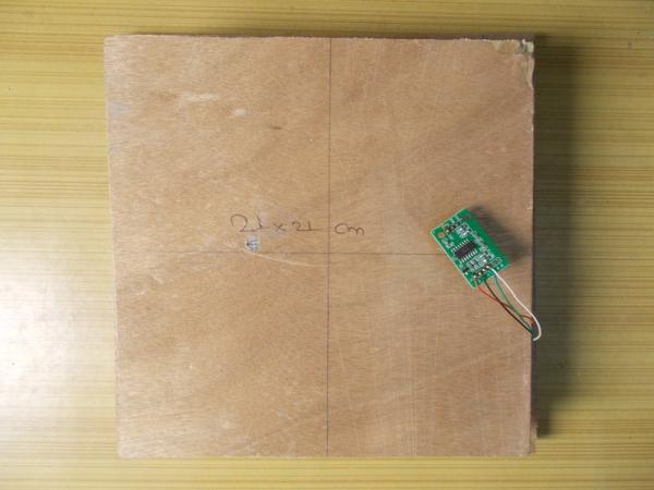
I got myself an 8 mm and a 12 mm thick plywood. On the 8 mm plywood I marked one square of 24×24 cm and another square of 21×21 cm and afterwards cut it using a jig saw. On the load cell you can find the arrow indicating the direction in which force must be applied. Keeping that in mind, I marked the mounting holes on the bigger plywood plate. The screws in my load cell are not identical, one is M5 and another is M4. I drilled the holes using a fitting drill bit. You can see I have the marked the center of the plate using pencil for accuracy. I kept the smaller plate on top of bigger plate so that it is in the center of it, leaving equal space on all the four corners, then I flipped it and made the required M4 hole on the smaller plate using the hole on bottom plate as guide. Then I tightened M5 nuts and bolts on the bottom plate and fixed one end of the load cell to it. Best way is to use mounting spacers, but I wasn’t able to find them near me, so I did it that way. Using the same method I attached the top plate to another end of the load cell and tighten it using a screw driver and nose plier.
This step is important because all the stress must only be experienced by the load cell if we want to measure the weight correctly.
The plates must be kept perfectly horizontal while measuring. To achieve that, I used this 1 inch thick MDF as standoffs and stick it using some glue to the bottom of the plate. I kept some heavy weight above the plate and left it to fry.
Step 4: Calibrate the HX711.
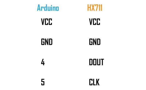
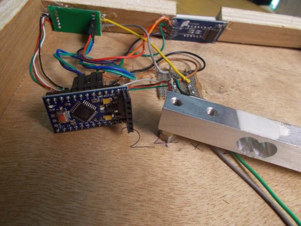
I connected the Load Cell to the ADC as shown in the picture.
Then, I connected the HX711 Module to Arduino (refer picture) and uploaded the calibration sketch attached in this step to the Arduino. I opened the serial monitor, kept a known weight on the plate and noticed the readings. What we have to do here is to determine the calibration factor of our load cell which gives the correct readings of the weight on the load cell. I used “a, s, d and f” and “z, x, c and v” to increase or decrease the calibration factor respectively (read the comments in the sketch).
When the reading shown on the serial monitor matches the known weight of the object on the load cell, I stopped, took a note of the calibration factor and disconnected everything.
Step 5: Test the Display.
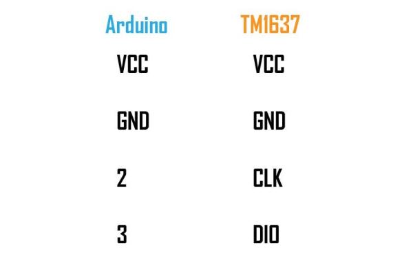
If you have to check your display, connect it to Arduino (refer picture) and upload the sketch attached in this step. The display should count from 0 to 999 and then print “DONE”.
Step 6: Make Sides.
I measured the distance between the top of the bottom plate and the top of the top plate and removed the top plate. I marked the length and breadth for four corners using the measured dimensions on the 12 mm plywood and then cut it. I made the front one beveled at 45 degrees so that when I put the display there, it is easy to read the weight. On the back side I cut a square for the barrel DC connector.
I drilled two holes on all the four sides of the bigger plate where I have to fix the sides I just cut. Then I drove the screws right in to the plywood with the sides on the bottom to fix the them at their places. For now, I left the back side and will fix it later.
Step 7: Make the Final Connections and Put Everything in Place.
I made the data and clock connections from both the modules to the Arduino. Always use hot glue to make the connections stronger, otherwise the wire will get loosen or broken if experienced stress.
To distribute power, I soldered two copper wires to a small perfboard and I will connect the power and ground wires of the modules and the Arduino right into it. While I was at it, I also soldered the DC barrel connector’s positive and ground to the copper wires. Upload the final sketch to Pro Mini before going further.
I soldered the Vcc and ground of the HX711 from the top of the headers to the distribution board and I connected the display module’s Vcc and ground to the HX711 using female headers. This way both modules are connected to the power supply. For the Arduino, I used another set of female headers and soldered it to the distribution board.
After all connections were made, I applied 5 Volts from an adapter to the circuit and everything was working fine. There are some fluctuations ha can be noticed. Those are due to the power supply. The cleaner the power supply the lesser will be the fluctuations. It was even more, when I powered the circuit using Arduino’s power supply but using an adapter seems to reduce the fluctuations. So make sure you use a clean power supply as averaging the readings or adding a capacitor won’t help. Best method is to use a separate linear voltage regulator for HX711 module.
Using hot glue I secured everything keeping in mind that they will not get in way if the top plate comes downward due to the weight on it and after that I screwed the top plate in place making sure that the corners do not touch.After I was satisfied, I glued the barrel connector to its place and also fix the back side using some hot glue. I should’ve used screws but this works too.
Keep one thing in mind though, while powering it on make sure no weight is kept on the plate as it will lead to wrong readings. Power it on first, then put the weight you want to measure.
Source: DIY Weighing Machine