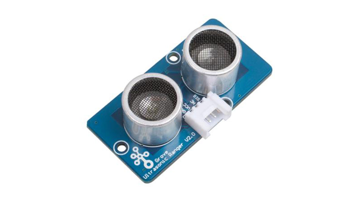
This project demonstrates the functioning of an “Ultrasonic Mono-pulse Tracker” built using two Grove ultrasonic sensors.
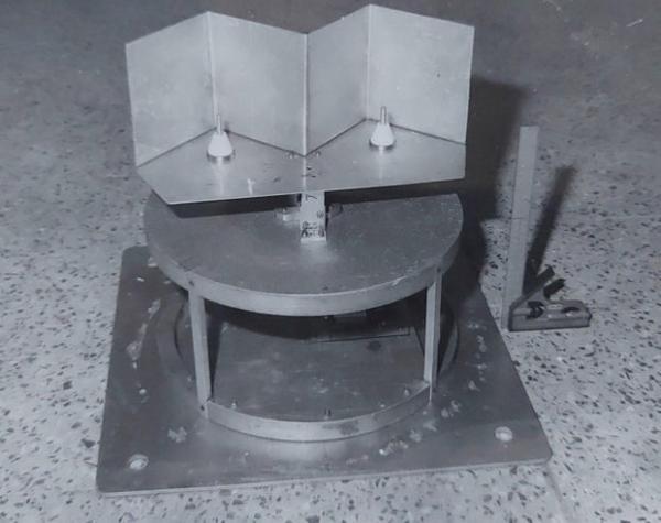
Two sensors facing forward at a small angle from each other are placed on a servo pedestal capable of rotating +/- 60 degrees based on commands from an Arduino UNO board.
The “Amplitude Comparison Mono Pulse” principle demonstrated here is based the amplitude signals derived from the overlapping beam patterns of the two sensors. The amplitude signals are obtained using a modification of the circuitry of the Grove sensor as shown in my earlier Instructable Arduino Analog Ultrasonic Radar
When we look at the difference in the amplitudes from the two beams we find a null when the tracker is pointed directly at the object being tracked. A error signal derived when the tracker is away from this direction is processed and fed as a rotation command to the servo-system to bring the track back to the desired position.
The inspiration for this project, the details and limitations are brought out in the following steps.
Step 1: Inspiration for This Work
Several years ago as part of my official tasks I built an L-Band antenna system to track the telemetry signals from airborne vehicles.
In this system two L-Band dipole antennas were placed in front of corner reflectors. The signals received from these were switched at 400Hz and fed to a L-band receiver. The automatic-gain-control signal from the receiver when phase-sensitive-rectified using the 400Hz reference provided the error signal to drive the servo system in the desired direction.
This passive mono pulse system inspired me to consider whether it was possible to build an active system similar to a regular mono pulse radar system using the simple ultrasonic rangers available to hobbyists.
These rangers typically consist of both a transmitter and receiver and based on the echo from targets provide the distance to the first target.
My earlier work on the Arduino Analog Ultrasonic Radar had resulted in a simple hardware modification which provided an analog output proportionate to the amplitude of echoes from targets.
With these factors in mind I decided to construct and demonstrate an “Ultrasonic Mono Pulse Tracker”.
Step 2: Hardware Modificition Revisited
Study of the Grove ultrasonic ranger circuit suggested that an analog signal proportional to the amplitude of the received echo from targets could be obtained from Pin 9 of the MCU.
A simple rectifier and low-pass-filter connected to this point provided an integrated output of the 8-Pulse response from targets.
In this project two sensors were used and the analog outputs fed to separate channels of the Arduino UNO.
Step 3: Beam Patterns and Software
Beam patterns were obtained using the Aj_Track_1.ino software.
A vertical rod of ~20mm diameter was placed at 40cm from the pedestal.
This software rotates the dual-sensors in azimuth over a +/- 60 degree angle. Simultaneously transmitting and receiving echoes from the two sensors and logging the results on the serial port.
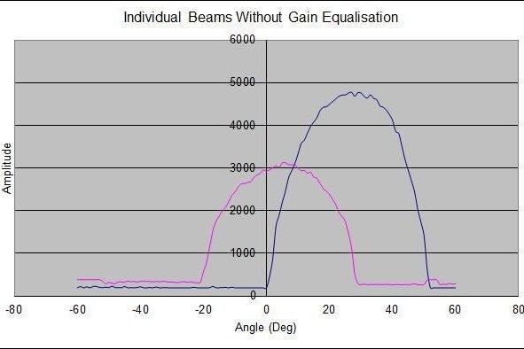
Amplitude values from the two sensors are plotted with respect to azimuth angle in both rectangular and polar coordinate systems.
The raw plot indicates a peak amplitude difference as the gains of both sensors are not equal. This is compensated by a suitable multiplication factor.
While a single beam shows a width of ~ 40 deg the difference beam is ~ 18 deg.
The difference beam also shows a typical S-Curve which provides the error signal for the tracking loop.
The Aj_Track_2.ino software implements the ultrasonic tracker. By evaluating the error signal at the current azimuth and rotating the servo cw/ccw as required it brings the error signal close to null and the tracker points to the object being tracked.
Step 4: Hardware Connectivity
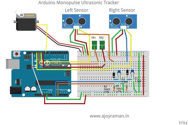
The Arduino is powered through the USB connector.
Connections:
Sensor:
Red — 5V
Black — Gnd
White — Modified for analog output Pin 9 of MCU
Yellow — Signal I/O
Servo SG90:
Red — 5V
Brown — GND
Orange — PWM
Arduino:
Servo PWM — Pin 9
Signal to Left Sensor — Pin 13
Test Signal 1 — Pin 12
Signal to Right Sensor — Pin 11
Test Signal 2 — Pin 10
ADC Loop Time Test — Pin 8
Detector Circuit from Left Sensor — Pin A0
Detector Circuit from Right Sensor — Pin A1
Step 5: Limitations and Summary
Typical practical tracking systems have beam widths of 2-3 degrees and a difference pattern of less than 0.5 degrees.
The large beam-width of the ultrasonic sensors leading to a large difference beam, limits both the range and position accuracy of the tracking system. Better sensors with better directionality would lead to improved performance.
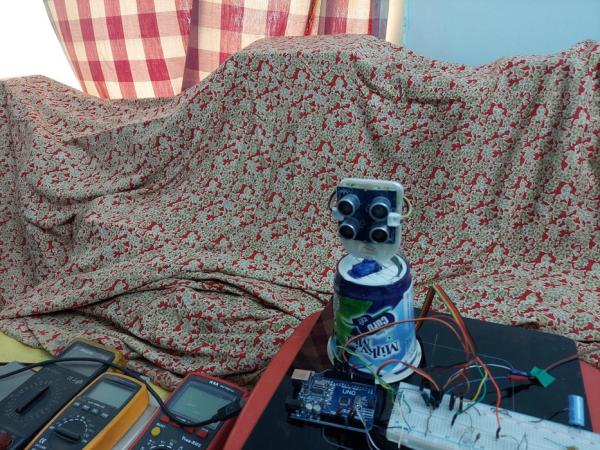
Tracking has been demonstrated in a single target configuration in my home laboratory. (Reflections from the background have been attenuated using a soft cloth cover).
However, in a practical scenario suitable software modifications for acquiring and locking onto the target of interest and range-gate tracking need to be provided for.
The analog hardware would also need to include a logarithmic-amplifier-detector to cover the full detection range and take care of the equivalent (radar-cross-section) of targets.
Source: Ultrasonic Mono Pulse Tracker