Summary of Ultimate Mosquito Swatter Mod for Gamer: Add Kill Counter, Sound, Rechargeable Battery.
This instructable explains how to hack an electric mosquito swatter to detect kills, add a 4-digit TM1637 score display, USB recharging, and sound effects using an ATTiny (Digispark Pro) and DFPlayer. It measures current across a 1 Ω sense resistor to detect arcs, processes signal noise with sliding-window standard deviation, and integrates off‑the‑shelf modules into a modified handle, with tips for shielding, soldering, and tuning thresholds.
Parts used in the Ultimate Mosquito Swatter Mod for Gamer:
- Electric mosquito swatter
- Digispark Pro (ATTiny board)
- DFPlayer audio module
- 1 Ω resistor (current sense)
- 1 kΩ resistor
- 470 µF capacitor
- 8 Ω speaker
- Micro SD card
- Li-ion rechargeable battery (salvaged)
- Battery charger board (USB charger)
- Potentiometer (about 1 MΩ used)
- Four-digit 7-segment display with TM1637
- On/off toggle switch
- Push button (reset)
- Wires (reused phone or ethernet cables)
- Soldering supplies, heat-shrink tubing, hot glue
- 3D printed handle or enclosure (or alternative mounting)
Where I live, from spring to autumn we have to compete for territory against tiger mosquito.
Local stores offer a impressive list of anti mosquito devices, candles, including sophisticated traps sold a few hundred euros, I even found one sold 2000€ – this give you an idea of how desperate people are to get rid of those invaders.
One of my favorite weapon to fight against mosquito is this cheap electric swatter, but to make this fight even more rewarding I thought I should upgrade my weapon.
In this instructable, I will show and explain how to hack an electric swatter to :
- add electronic to detect kills.
- add a 4 digit counter.
- make it usb rechargeable.
- add sound for a better experience.
My thought was that when an insect hits the wire mesh of the swatter and the electric arc occurs, there must be some electric variation on the swatter circuit. If I could find a place in the circuit that is readable by an arduino or attiny (that is between 0 and 5 volts) it would then be easy to count and display a score and to play some sound.
We can easily add sound/music capabilities to an attiny with a dfplayer module
Score would be displayed with a 4 digits 7 segment display which as an onboard tm1637 which allows to drive the display with only two wires (two IO pins of the attiny)
Because those electronic modules run at 5V and the swatter are usually running from 2 x 1.5 v batteries, I also upgraded the power part of the swatter with a usb rechargeable battery.
In other words, the upgrade is made with off-the-shelf electronic modules that are easily found, it is simple electronic, the only “complexity” is in the signal computation, but this is handled by the attiny through programming.
In this instructable I assume you have some knowledge of ardiuno and how it is programmed, if not you can find good tutorials on arduino site or explore arduino project on instructables.com
One more thing before starting, safety: electric swatter use high voltage (hundred of volts on the mesh when button is pressed) even if current is very low, be carrefull not to touch it or its internal circuit when battery is connected.
The Sticker says Caution keep away from children (and yourself)
Supplies
For this Ultimate Mosquito Swatter Mod for Gamer you will need :
- an electric mosquito swatter (there are several type of swatter circuit, this instructable and the program I suggest is adapted to one type of swatter, check the step ‘Open the swatter’ to verify your swatter matches what I use)
- digispark pro (convenient board with attiny, easily found online)
- dfplayer (easily found online)
- resistors: 1Ω, 1kΩ
- 8 Ω speakers
- sd card (a small capacity should be enough to hold a few sound files)
- li-ion rechargeable battery : salvage battery
- battery charger, something like this one
- potentiometer (I used a 1MΩ, it is not very important but a high value will limit current consumption through the potentiometer)
- Four digits LED display with tm1637 (make sure it is a 4 digit display + the TM1637 and not a 4 digit display only)
- capacitor : 470 µF
- on/off toggle switch
- push button
- wires (reuse old phone or ethernet cables)
For the tooling part, you will need a soldering iron, a hot glue gun and a 3D printer (or some creativity to modify the swatter handle…)
Step 1: How an Electric Swatter Works, How Can We Upgrade It?
Well, if you do not care about the way it work and just want your Ultimate Mosquito Swatter for Gamer, you can skip this step…
Resources explaining how an electric swatter works can be found on internet. (ie https://www.homemade-circuits.com/mosquito-swatter-bat-circuit/)
So it is oscillating circuit and a circuit to boost voltage up to hundreds of volts connected to the racket wire mesh.
Unfortunately, I could not find much to hook a attiny here (high voltage side is not directly usable due to the 5 volt limit of the attiny).
To work around this, my second thought was to measure current consumption. When an arc occurs on the net and the mosquito is fried, there must be some energy consumption that should be readable by an attiny.
The best way to measure this energy is to measure current consumption, and the easiest way to measure current is to measure voltage across a resistor, which an attiny can do.
So the only trick to count mosquitos is to insert a small resistor between the battery and the swatter circuit and monitor voltage across this resistor.
Beside that, I used already made electronic modules (one for each function : the sound, the display, the charger etc) so its is a fairly simple electronic project.
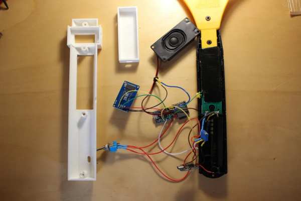
Step 2: Plan for the Circuit
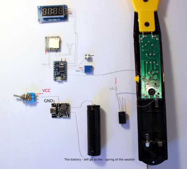
The main components added are
- attiny (digispark pro)
- dfplayer
- USB charger and the battery
- display
- reset button
- on/off switch
- potentiometer for volume adjustment
- two resistors and a capacitor
We need to lay them out so they can fit in the handle, digispark and dfplayer can be kept close from each other, allow the right wire length for this other component based on where they will be located in the final mod (ie the usb charger has a usb port onboard that will need to be accessible for recharge)
see images and photos
Step 3: Open the Swatter
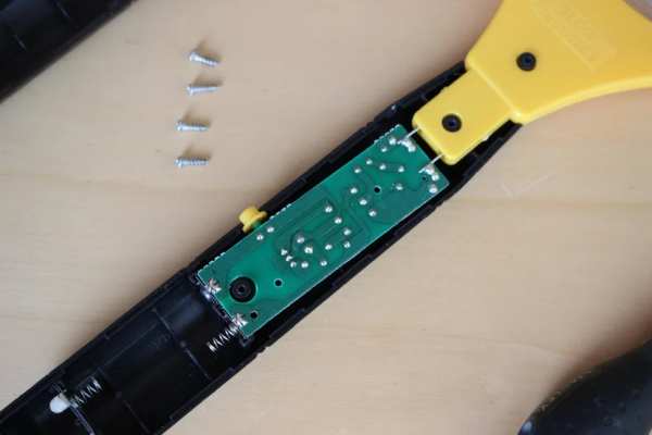
Remove the battery and open the swatter (it should be only a few screws).
It allows you to see how much room you have to place the add-on components but also check if your swatter matches what I use in this instructable…
The major difference to care about it the “location” of the push botton of the swatter. On mine, it is located between the + of the battery and the swatter circuit. If this is the case you are good to go (see photo).
On some swatter, this push button is located between the ground (-) and the circuit. In this case my modification and code will not work. I am pretty sure I can make it work with such swatter but it will need some adjustment on the hardware and software side. I will update this intructable once I have worked on this second type of swatter.
Step 4: Modify the Swatter
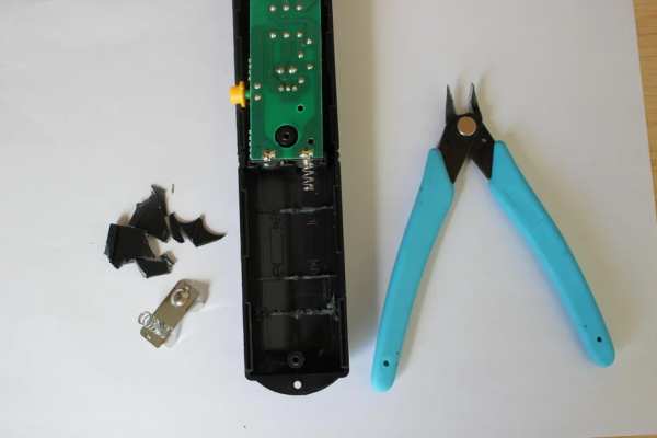
In this step we :
– make some room for the battery in the compartment that was design for two AAA battery (and reuse the battery connector for the rechargeable battery)
Step 5: Build the Circuit, Solder All Components
Now that we know what is connected where, we can proceed with the soldering.
Layout all components based on their final location in order to estimate the various wires lenght.
In the previous step, for clarity purpose I did not draw the ground and VCC (5V) wires, but all ground need to be interconnected, all VCC need to be interconnected.
For VCC, the digispark has 3 pin labeled 5V, they are linked together and can be used to redispatch to other components. Do not use the VIN of the digispark (VIN is a voltage input that need to be above 6V, we do not use that but rather the 5V ouptut from the battery charger).
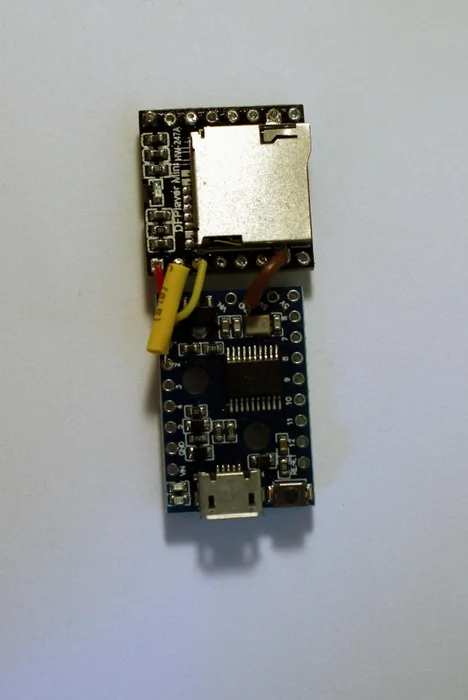
I suggest to start with the digispark :
- solder the digispark to the dfplayer.
- the digispark to the display, push button and potentiometer.
- use heat-shrink tubing to avoid contact and short cuts (like for the resistor between the digispark and the dfplayer).
Then, proceed with the swatter circuit, battery chager, on/off switch:
- battery – to charger battery – input
- battery + to charger battery + input
- 1 ohm resistor on the swatter circuit (+)
- the capacitor on (+) and (-) of the swatter circuit, watch the capacitor polarity !
- pin A12 of digispark to the push button (the push button has two connectors, one connected to the battery +, A12 goes to the other one)
- use heat-shrink tubing to avoid contact and short cuts (on the capacitor, on the resistor, etc )
See pictures for the progression…
Step 6: Isolate the Display From the Swatter Circuit
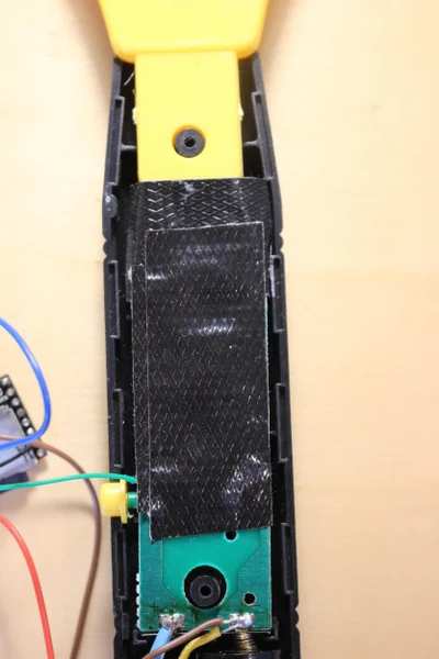
During my firsts tests I had display issues…the display would turn off or go crazy when a mosquito hit the mesh of the swatter.
I suspect it was due to electronic disturbance generated by the high voltage variation impacting the display circuit and connections.
The fix is simple, some tape on the circuit, aluminum foil (electromagnetic shield) and tape again.
Of course, do not place the aluminum foil directly on the circuit or it will create shortcuts…
Step 7: Load Sound on SD Card
Sound played by the dfplayer are stored on an SD card.
I kept it simple, formated the card and copy my selected sounds
this is
- a sound played at power on (“get ready to the next fight”)
- a “monster killed” sound
- a “level up” sound
- some sound files played randomly when a kill is detected.
Once on the card dfplayer will play sounds based on a “track number”.
I could not find a clear description of the link between the dfplayer track number and the files on the SD card.
Based on observation, I suspect files are not sorted based on their name but rather with their inode number on the card (which can be seen with “ls -id” on linux)
ls -id * | more
647 1_Monster_kill.mp3
648 2_mixkit-final-level-bonus-2061.wav
649 3_get_ready_to_the_newt_fight.mp3
650 mixkit-arcade-retro-scoring-counter-273.wav
651 mixkit-arcade-video-game-bonus-2044.wav
652 mixkit-arcade-video-game-scoring-presentation-274.wav
653 mixkit-game-bonus-reached-2065.wav
654 mixkit-game-experience-level-increased-2062.wav
655 mixkit-winning-an-extra-bonus-2060.wav
I think that if you start from a freshly formated card, the sequence of track number / inode will be the order of the copy of the sound files (ie first file copied on the card will have tranck number 1)
In my suggested code, the file/track selection is done with setTrack :
 // 0 is random betwen tracks 4 to 9
 // 1 is monster kill = track 1 (listed by inode on card (ls -id))
 // 2 is level up
 // 3 is power on
 if (sound_type==0)  setTrack(int(random(4,9))); //SD card contains 9 files
 if (sound_type==1)  setTrack(1); // monster kill
 if (sound_type==2)  setTrack(2); //level up
 if (sound_type==3)  setTrack(3); //power on
So you could modify that part to have a match between the action (sound_type) and the track played.
Step 8: Print a New Handle
In case you are modifying the same swatter as used here, you could directly print my handle design.
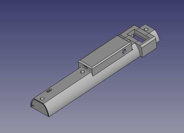
If not you will have to design your own…
However some swatter have quite big handles with almost nothing in it, it might be possible to fit the add on circuit in without printing anything. You still need to find a place for the display and speaker.
Step 9: Assemble Everything
I used a hot glue gun to secure the parts in their final location.
The speaker is also glued directly on the swatter.
Step 10: Where Is the Mosquito ? Math and Stats to the Rescue
Once again, if you do not care about the way it works and just want your Ultimate Mosquito Swatter for Gamer, you can skip this step…and maybe come back later.
Once all components are soldered together if you load a simple program on the attiny that only do a analogRead(A12) and look at the raw data… it is a bit disappointing, raw data looks very noisy and you cannot tell where/when on the graph a mosquito (or something else, I did not wait for mosquitos to hit my racket to debug the code 🙂 ) hit the mesh of the racket (see figure 1).
Averaging if a good way to cleanup part of the noise, and my idea was to compare the last average to a “long term” average, but well it was a bit disappointing too (see figure 2).
Next step is to read and learn what smarter people do…https://www.iese.fraunhofer.de/blog/change-point-detection/
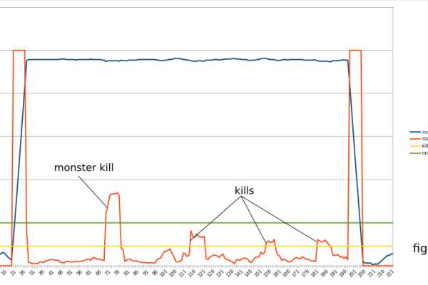
This looks exactly what I am looking for, the calculation of the standard deviation of my signal should allow me the detect those kills (see the animation “Animation of change point detection via sliding window ” on the link above).
Applied to our setup it give the following results (figure 3). In my program I calculate the square of the standard deviation, we can see it reaches very high values when I push or release the racket button (this is expected, the signal goes from 0V to close to 5V), but once those phases are excluded, I can monitor this standard deviation and assume that if it goes to some high values, we have a disturbance in the circuit which must be a mosquito kill (figure 4) !
Now that we know how to find a kill, the rest is easy (play a sound, increase score).
To be honest and more accurate, some more things were added :
– a 470 uF capacitor (which by it self provide some more noise filtering and serve as some sort of power bank when high current is needed)
– we have a two level averaging mechanism (you will see in the code that I measure 5 times in a raw the voltage on pin A12, average it and then store this averaged value for the sliding window of the standard deviation calculation)
Step 11: Load Program on the Digispark Pro
This is pretty straighforward, the attiny can be programmed using the arduino IDE
instructions : http://digistump.com/wiki/digispark/tutorials/connectingpro
Some explanations on the code I am suggesting:
in the setup() funtion, we initialize the serial communication needed for the dfplayer, read the potentionmeter value to adjust the volume (it is read only once at setup time to avoid using cycles for this, which means the swatter woud need to be power off /on to take into account a volume adjustment).
Samething for the counter reset, I you want to reset score to zero, you need to push the reset button, power on the swatter and wait for the display to show “0”.
It then read the score stored in EEPROM.
It sets Brightness of the display (otherwise it remains off).
In the loop() function we basically process the average of the swatter power process_average() and the square of the standard deviation which tells us if we have a kill or not (process_std_dev() )
Step 12: Update the Digispark Micronucleus (optionnal)
The digispark micronucleus is the piece of code in charge of “starting” the digispark.
It checks if we are trying to upload a new program and if not start the program already loaded.
The problem is that it waits for 6 seconds for this check, which is fairly long when your are waiting for your swatter to be ready for a hunt…
Thanksfully there are some variants of the micronucleus with a different checking mechanism. If you update your micronucleus following those instructions (use the “recommended” config), the swatter will be ready after one or two seconds only.
Instructions : https://github.com/ArminJo/micronucleus-firmware
Reload your program after updating the micronucleus firmware.
Step 13: Troubleshooting…
Hopefully you will not have to read this but…some tips just in case…
- not much work…check wire and solder
- if the swatter restarts by itself (you hear the starting sound but have not switched on/off), recharge the battery
- the swatter shutoff by itself after about 30 seconds.
- some USB charger circuit have an automatic standby mode (that was the case for mine which is using chip IP5306) and will go in standy mode if less than some amount (45mA for the IP5306) of current is consumed.
- the first workaround possible is to press the swatter button on a regular basis…like every 20sec. this would maintain the power up
- the board (with IP5306) has a “key” feature allowing to power on or off. it is labeled “K” on the board. Solder this to pin 10 of the digispark. the watchdog() function on the code I suggested will keep the power up.
- if the swatter is really bad at detecting or wrongly detect…well you may have to do some code adjustment…
I spent hours tuning this device and its code. The major difficulty is to monitor what is going on…
If you want to use the USB port to display some variables, you have to modify the code in order to use the DigiCDC library and remove the SoftSerial (which is used for the 4 digit display). But more over when doing so, you get power from the USB port and not the battery charger port and this makes a big difference…The quality of VCC impacts a lot our calculated average and standard deviation…
In other words any tuning performed while connected on the USB will probably not work when running from battery…
One way to get some little information is to use the display itself (ie display the last standard deviation when the reset button is pressed)
Knowing that, you can try to adjust the following values in the code which impact (a lot) our detections:
the number of samples taken for a single read :
int samples=10;
The size of the average sliding window :
int nbr_slot=15;
int value[16];  // array of (nbr_slot + 1)
The standard deviation thresholds :
int threshold=110;
int monster_threshold=250;
Things could be done differently of course, If you improve the swatter, find simpler way to do it, design a handle for other models.
Source: Ultimate Mosquito Swatter Mod for Gamer: Add Kill Counter, Sound, Rechargeable Battery.
- How does the mod detect mosquito kills?
By measuring voltage across a 1 ohm resistor in series with the swatter and computing a sliding-window standard deviation to detect high disturbances when an arc occurs. - Can I use off-the-shelf modules for sound and display?
Yes, the project uses a DFPlayer for sound and a TM1637 four-digit display module driven by the Digispark Pro. - How is the swatter made USB rechargeable?
By replacing the original batteries with a Li-ion rechargeable battery and adding a USB battery charger board accessible from the handle. - What safety precautions are mentioned?
Do not touch the high-voltage mesh or internal circuits while the battery is connected; the swatter uses hundreds of volts on the mesh. - Does the project require code changes to tune detection?
Yes, detection is tuned via code parameters like samples, sliding-window size, and standard deviation thresholds. - How do I prevent display interference when a kill occurs?
Shield the display circuit using tape and aluminum foil (without causing shorts) to isolate it from high-voltage disturbances. - What should I do if the charger board goes into standby?
Use a watchdog in the Digispark to toggle the charger key pin or periodically press the swatter button to keep current draw above the standby threshold; solder charger K to Digispark pin 10 if supported. - How are sounds organized on the SD card for DFPlayer?
Tracks are played by track number; observed mapping corresponds to file inode/order when copied to a freshly formatted card, so copy files in desired sequence. - Can I fit components inside the original handle?
Depends on swatter model; some handles have enough room, otherwise print a new handle or redesign mounting to fit components, display, and speaker.