There are already some NFC jukeboxes.
Off the shelf like those “Toni” boxes. For do-it-yourself: lots of instructables.
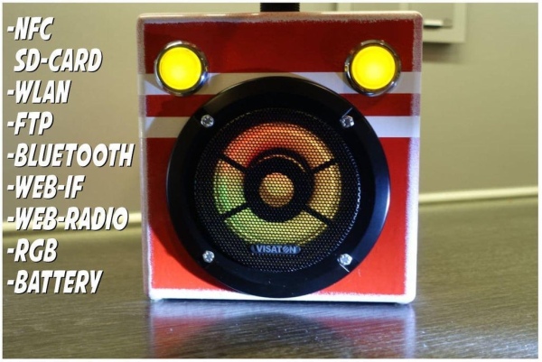
This device should cover as much as possible, which could come into question sometime and somehow.
It should have as few weak points as possible, (in which a 3-year-old could put things).
Easy to use, easy to maintain and hard to destroy.
And there I came across a project that uses an ESP32 as a base.
In addition a NFC reader, a small amplifier … stuff.
And all in a very sturdy box made of wood.
No openings, foolproof.
NFC, WLAN, FTP, BT … hellyeah 🙂
How loud at start, how bright, when go to sleep??? … everything in one webinterface.
Supplies
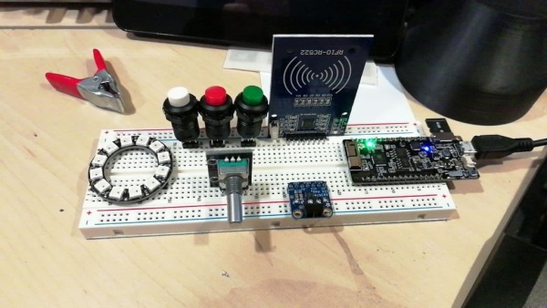
Basicly you will need an ESP32.
There are many options. I’ve bought one with an build in sd-reader.
- ttgo t8 v1.7 esp32 4MB PSRAM
You should look at least for PSRAM. Online-Radio works realy much better.
And if i would build it againg, i would look for more RAM (to use the OTA feature).
biologist (https://forum.espuino.de/u/biologist) has some nice boards to solder all the stuff on it.
I can highly recommend his boards (but you don’t need them).
Depending on which ESP you use, you still need an
- SD reader module
I would choose one with SD-MMC (over SPI) as it is considerably faster:
SD_MMC:
FTP (up): 3:57min => 298 kiB/s
FTP (down): 3:45 => 314 kiB/s
HTTP: 3:10min => 372 kiB/s
SPI:
FTP (up): 6:38 => 178 kiB/s
FTP (down): 5:38 => 208 kiB/s
HTTP: 6:24min => 184 kiB/s
You may need an external Power-Supply. I’m using a quite special USB-Powerbank.
It delivers 3.3V and 5V with common ground. That makes wiring much simpler.
https://de.aliexpress.com/item/4000112237395.html?spm=a2g0s.9042311.0.0.5d514c4dogsadB
If you use an external powerbank, however, you can no longer see the current battery status via the RGB LED ring.
As amplifier I use the classic “Max” from Adafruit.
- https://de.aliexpress.com/item/32999952454.html
By the way, I operate it with 5Volt to get the full volume.
- NFC-Reader (Arduino)
- Rotary-Encoder
- Arcade-Buttons, new LEDs
- magnetic usb-loader
- visaton speaker (4ohm)
- wires, wires, wires
- LED-RGB-Ring (i’m using 12 LEDs)
- some transistors / mosfets / resistors
- 9mm wood
Tools:
It depends on your skills and what you want to use as a box.
I used a drill-press, jigsaw, miter-saw and a router. But…
you could also use an old speaker and put all electronics in it.
Step 1: Software
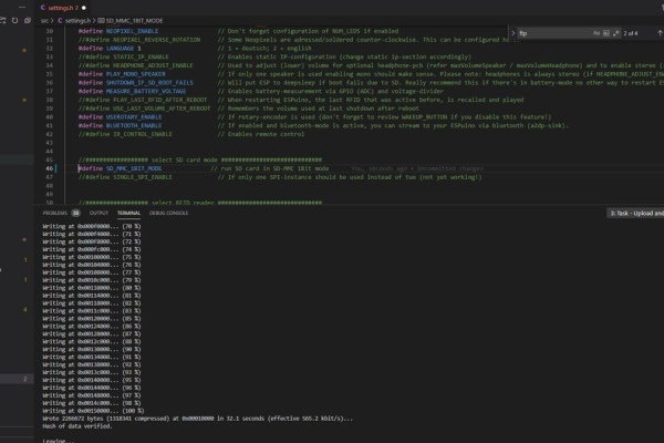
OK. One hurdle. Software.
– Install Visual Studio Code (https://code.visualstudio.com/)
– Insert Platformio (https://platformio.org/install/ide?install=vscode)
– install Git (https://gitforwindows.org/)
– clone the current state (git clone https://github.com/biologist79/ESPuino.git)
- import this folder into Platformio as a project
– learn a little bit about Visual Studio (crash course)
– compile the first code several times and then push it to the ESP
Detailed instruction if you get stucked: https://github.com/biologist79/ESPuino#getting-started
All compiling-options can be done at a later step. There are several tweaking-options.
But at first you should be able to compile and upload and to see a serial output.
If it worked, you are able to connect to the Wireless Access Point with its own webinterface, which will lead you through the WLAN configuration.
Now it’s time to get the hardware working. Power off your ESP and start with a breadboard.
Step 2: Connecting
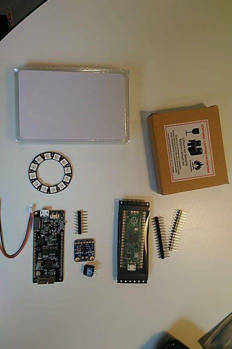
I prebuilt everything on the plug-in board. To provide everything with cables is a bit wobbly and may well lead to loose contacts, but you can be sure that everything will run in the end.
I can only advise this step to everyone. Troubleshooting directly in the box is hell.
One problem is the amplifier. You should solder it as directly as possible to the ESP. Out of three amplifiers, three were problematic.
The LED-ring, although 5Volt, runs fine with 3.3 Volt.
You can, as long as you don’t turn up the LED ring and the volume, run the whole system over the USB.
Personally, I always advise against this. If I build a system that will end up running on battery, then I test it on battery and not with a constant current source.
For debugging you can use the webinterface to a large extent.
What needs to be connected to what depends on the selected ESP.
For me, I was able to proceed according to these instructions:
https://forum.espuino.de/t/was-wie-muss-verdrahtet-werden/42
The whole thing has to be adjusted a little bit with the code. But this is very well documented.
If a button does not work, then either the pin is wrong, or a pin is used that has no internal pullup. Then just add a 100Ohm resistor and the button should work.
The checklist:
– Create a folder on the SD card in the web interface and transfer data
– assign this data to a nfc-card
– assign another nfc-card for activating the FTP
– test both cards
– Test FTP connection (in the client: only one connection at a time and set the character set to CP437)
– Start music with one card and test all buttons
– assign internet radio (any station) to a card and test it
– Test Bluetooth
Step 3: Tuning
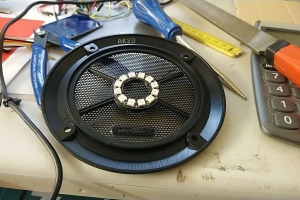
If all this works, then you can think about moving functions. I put e.g. PLAY/PAUSE on the rotary button.
This is done by software in the code and has to be recompiled.
I put the RGB LED ring behind the cover of the speaker membrane and thus let indirectly illuminate the speaker.
Attached is the stl for this. If you want, you can also have the Fusion360 file. Just send me a message.
For my powerbank I have set a separate button. The powerbank has a pushbutton. I have simply extended its contacts and set a separate button.
I also swapped all the LEDs in the Arcad-buttons, as the originals were too dim for me on 5 volts.
They are also still connected to the ESP. But via a Mosfet.
You could also connect them directly to the powerbank, but then the auto-off would no longer work.
To power the powerbank, I use a magnetic charging adapter. The big advantage is that even our 3 year old can charge the box. And if he pulls the box from the table while it is still charging, nothing happens but that the cable comes off. No tearing off of plugs or sockets
Step 4: Use an Old Speaker or Build Your Own 🙂
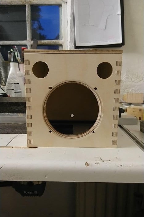
From hereI used visaton’s values as a guide to determine the correct volume. I then built it from 9mm birch multiplex. Build with glued finger-joints. To test the stability, I stood on it. 🙂
For really clean circle cutouts I have made laser templates and then milled with the TrimBit with my router.
The fingerjoints I have also made with the router. A kind of step-and-repeat, in which I have previously sawed pieces of wood that have exactly the same thickness as the bit.
I milled the cover plate all around so that it doesn’t lay on that thick. And it makes the whole thing even more stable.
For the cutout of the NFC cards I made a frame with the 3D printer and then worked with the router and the copy sleeve.
Step 5: Pre-Test
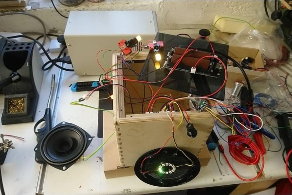
A few parts had to be chewed on before it could be finally glued together.
The NFC reader and the encoder in the lid.
After that, I installed everything for testing. I used 4mm acrylic for the bottom. The powerbank is also screwed onto it.
The base itself is screwed into the wood with small press-in threads.
Then finally the first real test 🙂
Step 6: Colouring
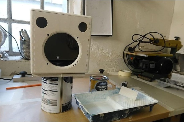
First of all, grind grind and grind.
Until you think it’s enough. And then sand again.
Then the usual build up:
– prime
– fill
– sand
– white
– mask
– paint
I have built it completely on solvent based paints. In contrast to acrylic, the surface is much harder later.
Step 7: Final Assembly
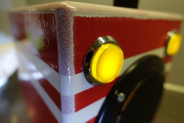
This is by far the most beautiful part of such a project. Finally, what belongs together comes together.
With my box, the order was simple. I had to start from the lid and then work my way to the powerbank in the bottom.
I would not have thought that it is quite tight in the relatively large box, if you still have to solder something.
Step 8: Creating NFC-Sticker
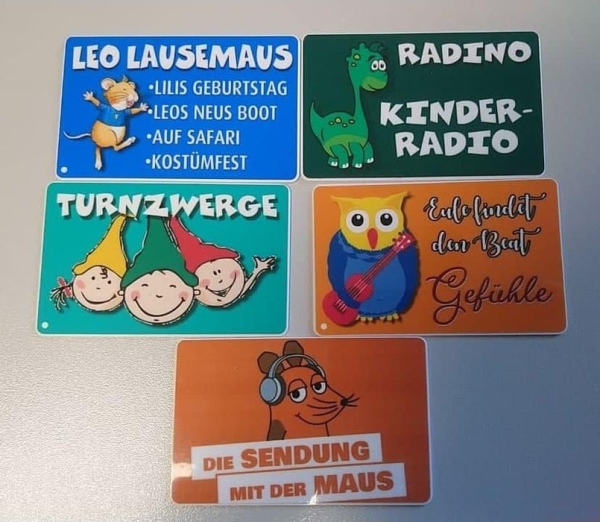
Of course, the cards should still look beautiful. I have access to a very large latex printer. I can produce stickers and cut them to fit for the nfc-cards.
I design the motifs on the PC in CorelDraw.
I’ve addad a small white point on every card which works offline.
Step 9: Final Thoughts
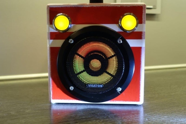
I can’t remember the last time I had this much fun on a project.
And I can’t think of anything that could be improved about it.
It also has the option for a remote and headphones if you want them.
It has very much power and all can be configured in the webinterface.
I’m going to make another little pocket to put on the back. Then a few cards can go in there.
And attach a carrying strap.
If you liked this one:
then please vote for me in the audio contest 🙂
Source: Ultimate Kids Musicbox ESP32 Based
