Summary of DCF77 master clock MK2
This article details the construction of a DCF77 Master Clock MK2, an Arduino-based timekeeping device that decodes atomic signals from Mainflingen, Germany. Utilizing Udo Klein's DCF77 library, the clock maintains high accuracy through auto-tuning quartz crystals and features dual displays: green 7-segment LEDs for primary time and an I2C LCD for detailed data. It includes PIR-activated display shutdown, Bluetooth connectivity for remote monitoring, and automatic leap second adjustments. The project reuses an oak case from a 2004 build but modernizes the internal logic using an Arduino 328 microprocessor instead of legacy logic chips.
Parts used in the DCF77 Master Clock MK2:
- Arduino 328 Microprocessor
- DCF77 Library by Udo Klein
- 32.768KHz Quartz Crystal
- Six 1" (26mm) Green LED 7-Segment Displays
- MAX7219 Driver
- 4x20 I2C LCD Display
- LDR Sensor
- Pulse Width Modulation (PWM)
- Passive Infrared (PIR) Module
- EZ Link Bluetooth Serial Board
- Oak Case
Features
Arduino 328 Microprocessor is used to decode and display Time & date from the DCF77 “Atomic” Clock in Mainflingen near Frankfurt Germany
The DCF77 signal is decoded using the fantastic new DCF77 library written by Udo Klein meaning the clock stays in sync and keeps perfect even with a massive amount of noise on the received DCF77 signal
Udo Klein’s DCF77 library continually “Auto Tunes” the quartz crystal so in the rare event the signal can’t be decoded the clock remains accurate within 1 sec over many days
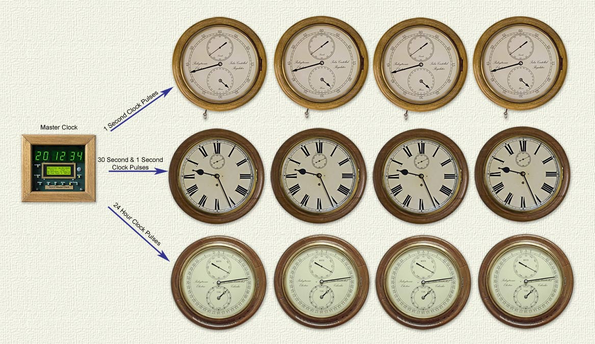
The clock provides the following pulses to drive slave clocks 1 sec alternating, 30 sec, 1 min , 1 hour, 24 hr, 15 min chime of quarter hours, hourly chime of hours
Primary display of time in hours, minutes & seconds are displayed on 1″ (26mm) green LED 7 segment displays
Secondary 4×20 I2C LCD display is used to display time & date, fast or slow seconds, summer winter correction, display brightness, sync information, signal quality, auto tune’d frequency, auto tuned quartz accuracy and summer winter time mode
The primary and secondary displays are auto dimmed using and LDR and Pulse Width Modulation
The primary and secondary displays are shutdown during daytime and are activated by Passive Infrared detection when the clock detects someone entering the room
Manually triggered automatic Summer/Winter time correction of 30 second slave clocks
Blue-Tooth link for programming, clock pulse status and PIR adjusting
Auto leap second adjustment of 30 second slave and 1 second slave clocks time and date of leap second can be read via Blue-tooth on your PC or Android mobile or tablet
Recording of fast or slow 1 second slave clock pulses on the LCD display as well as time and date stamping of last fast or slow pulse accessible by Blue-Tooth on your PC or Android mobile or tablet
Design
I designed and built my old Master Clock see photos below in 2004 using a 32.768KHz quartz crystal and logic chips to display the time and derive the pulses to drive all my slave clocks. It also has a DCF77 decoder board that again uses logic chips to decode the DCF77 signal and get a 1 second synchronising pulse to keep the clock on time. The technology used in this clock was actually out of date when I built it as I used the technology I had leant about at college in the late 1970’s. I soon found out from comments that no one really used logic chips for this sort of thing anymore and why had I not used a Microprocessor?
After a few years I gave microprocessors a try by building a PIC Microprocessor based Calendar Slave using Oshon Soft Basic , a Meter Clock using Picbasic Pro v3 and a DCF77 Master Bracket Clock using an Arduino 328.
I decided to use Arduino to control my new Master as it seemed tailor made for my basic programming skills as most of the complicated work is done by the people who design and then share the libraries. Arduino is very well supported hardware wise and many complete parts can be purchased ready built as building block for projects.
A MAX7219 drives the primary display, a 4×20 I2C LCD is used for the secondary these help keeping wiring and Arduino 328 pin use to a minimum.
I kept the same type of Oak case used in my old master Clock as it fitted 6 x 1″ 7 segment displays perfectly and gave me space to fit in all the other modules.
I have used a PIR module for display shutdown/wakeup with it’s own timer and sensitivity adjustment as this uses only 1 pin of the Arduino 328.
A EZ Link Bluetooth Serial Board module enables me to program the clock and read data from it remotely from my desktop PC.
For more detail: DCF77 master clock MK2
- How does the clock maintain accuracy when the signal is lost?
The DCF77 library continually auto tunes the quartz crystal to keep the clock accurate within 1 sec over many days. - What pulses does the clock provide to drive slave clocks?
It provides 1 sec alternating, 30 sec, 1 min, 1 hour, 24 hr, 15 min chime of quarter hours, and hourly chime of hours. - Can the display brightness be adjusted automatically?
Yes, the displays are auto dimmed using an LDR and Pulse Width Modulation. - When are the displays activated or deactivated?
Displays shut down during daytime and activate via Passive Infrared detection when someone enters the room. - How can you adjust Summer/Winter time manually?
You can trigger manual automatic Summer/Winter time correction of 30 second slave clocks. - Does the system support leap second adjustments?
Yes, it has auto leap second adjustment for both 30 second slave and 1 second slave clocks. - What device is used to read fast or slow pulse data remotely?
Data on fast or slow pulses and time/date stamping is accessible via Blue-Tooth on a PC, Android mobile, or tablet. - Why was the Arduino chosen over logic chips for this design?
Arduino was selected because it is well supported, simplifies programming with libraries, and reduces wiring complexity.