
Summary of Two Wire Arduino Knight Rider
This tutorial demonstrates interfacing eight LEDs with an Arduino using only two pins by employing a PCF8574 I/O expander IC. The project creates a "Knight Rider" light display on the breadboard. It requires specific resistors, capacitors, and LEDs connected via the I2C bus (pins A4/A5) to expand the Arduino's output capabilities efficiently.
Parts used in the Two Wire Knight Rider:
- Arduino Uno board
- USB cable
- Wire links
- Breadboard
- Two 2k2 resistors
- Eight 470 ohm resistors
- One 100n capacitor
- One PCF8574P IC
- Eight LEDs (red or green)
This tutorial shows how to interface eight LEDs to an Arduino using only two Arduino pins. This is made possible by using a PCF8574 I/O expander IC. A “Knight Rider” display is shown on the LEDs.
Prerequisites
Complete tutorial 4 – Arduino Knight Rider. Be able to use DIP IC packages, e.g. from tutorial 17.
Components
In addition to an Arduino Uno board, USB cable, wire links and a breadboard, you will need:
| QTY | PART | DESIGNATOR | NOTES | TYPE |
|---|---|---|---|---|
| 2 | 2k2 resistors (red – red – red) | R9, R10 | 1/4W 5% or better | Resistors |
| 8 | 470 ohm resistors (yellow – violet – brown) | R1 to R8 | ||
| 1 | 100n capacitor | C1 | Non-polorized capacitor | Capacitor |
| 1 | PCF8574P | U1 | 4047 IC e.g. CD4047 (14 pin IC) | Semiconductors |
| 8 | LEDs | D1 to D8 | LEDs – red or green 3mm or 5mm diffused LEDs |
Circuit Diagram
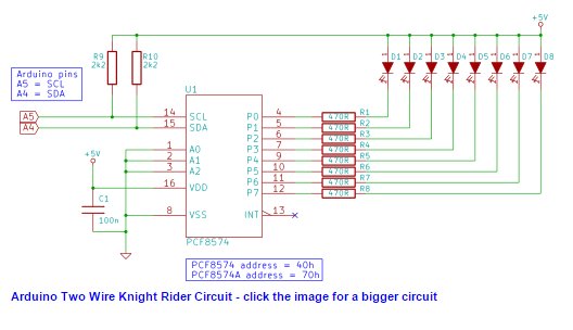
In this circuit diagram, the Arduino board is not shown. Only the pin labels of the Arduino pins to be connected to the PCF8574 (U1) are shown. The points marked +5V are to be connected to the Arduino 5V pin. The inverted triangle (GND) is to be connected to one of the Arduino GND pins.
Building the Circuit
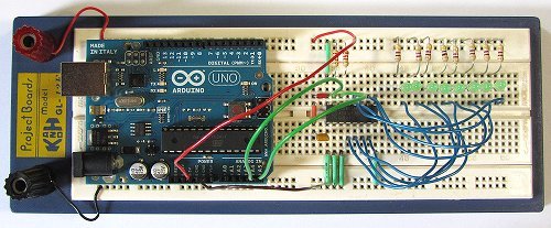
The photo below shows the complete circuit built on breadboard. Click the photo for a bigger image.
The suggested sequence of building the circuit is:
- Insert the PCF8574 IC
- Make power and ground connections to the IC
- Connect pin 1, 2 and 3 of the IC (U1) to ground
- Insert capacitor C1 (100n) and wire it between power (5V) and ground (GND)
- Insert the eight LEDs with anodes (longer pin) on the left
- Connect resistors R1 to R8 between the LED anodes and the top breadboard rail (5V)
- Wire the cathode of each LED to the correct pins on the IC
- Connect R9 and R10
- Connect the two wires from Arduino pins A4 and A5 to the IC
- Connect the Arduino 5V to the top breadboard rail and GND to the bottom breadboard rail
You may have noticed that the breadboard circuit swaps the position of the LEDs and resistors from the circuit diagram – e.g. R1 and D1 swap positions. This will make no difference to how the circuit operates. It has only been done to simplify the breadboard circuit.
Programming the Arduino
Copy the two_wire_knight_rider sketch below and paste it into the Arduino IDE.
/*--------------------------------------------------------------
  Program:      two_wire_knigh_rider

  Description:  Uses a PCF8574 IO Expander IC on the Arduino
                TWI bus to interface 8 LEDs. A "knight
                rider" display is shown on the LEDs.

  Date:         25 April 2012

  Author:       W.A. Smith, http://startingelectronics.com
--------------------------------------------------------------*/
#include <Wire.h>

// address of PCF8574 IC on TWI bus
#define IO_ADDR (0x40 >> 1)

void setup() {
  Wire.begin();        // initialize the I2C/TWI interface
}

void loop() {
  static unsigned char data = 0x01;  // data to display on LEDs
  static unsigned char direc = 1;    // direction of knight rider display

  // send the data to the LEDs
  Wire.beginTransmission(IO_ADDR);
  Wire.write(~data);
  Wire.endTransmission();
  delay(70);  // speed of display

  // shift the on LED in the specified direction
  if (direc) {
    data <<= 1;
  }
  else {
    data >>= 1;
  }
  // see if a direction change is needed
  if (data == 0x80) {
    direc = 0;
  }
  if (data == 0x01) {
    direc = 1;
  }
}
For more detail: Two Wire Arduino Knight Rider
- How many Arduino pins are required for this project?
The project uses only two Arduino pins, specifically A4 and A5. - What component allows eight LEDs to be controlled by just two pins?
A PCF8574 I/O expander IC is used to interface the eight LEDs. - What visual effect does the code produce on the LEDs?
The program displays a Knight Rider pattern on the LEDs. - Which library must be included in the Arduino sketch?
The Wire.h library is required to initialize the I2C/TWI interface. - What is the delay time set for the LED display speed?
The delay is set to 70 milliseconds between updates. - How should the resistor values be selected for the LEDs?
Eight 470 ohm resistors are used for the LEDs and two 2k2 resistors for other connections. - Can the position of LEDs and resistors be swapped on the breadboard?
Yes, swapping their positions simplifies the circuit without affecting operation. - What voltage rail connects to the top breadboard rail?
The 5V power from the Arduino connects to the top breadboard rail.
