
This lab guides users in constructing an alternative computer mouse using an Arduino Leonardo. By integrating pushbuttons, the project enables directional control (left, right, up, down) for the cursor. The tutorial emphasizes distinguishing between continuous digital input reading and detecting state changes before activating mouse commands to ensure safety during development.
Parts used in the Alternative Computer Mouse:
- Arduino Leonardo
- Breadboard
- Pushbuttons (5 total)
- 10-kilohm resistor
- Wires
Overview
In this lab, you’ll build an alternative computer mouse using an Arduino Leonardo using pushbuttons to move the mouse left, right, up and down. You’ll see the difference between reading a digital input continually and reading for a change of state.
(:toc Table of Contents:)
Parts
For this lab you will need the following parts:
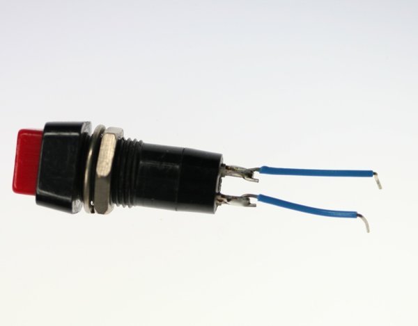
Click on any image for a larger view
NOTE: The sketches contained in this lab will cause the Arduino Leonardo to take control of your mouse. Make sure they’re working properly before you add the mouse commands. The example doesn’t introduce the mouse commands until the end of the lab. Instead, messages are printed to the serial monitor to tell you what should happen. When you’ve run this and seen the serial messages occurring when you think they should, then you can add the mouse commands safely.
The sketches here will work on an Uno until you add the mouse commands. So you can test this on an Uno simply by commenting out any line that says Mouse.begin() or Mouse.move().
Prepare the breadboard
Connect power and ground on the breadboard to power and ground from the microcontroller. On the Arduino module, use the 5V and any of the ground connections:
Attach a pushbutton to digital pin 2. Connect one side of the pushbutton to 5 volts, and the other side of the pushbutton to a 10-kilohm resistor. Connect the other end of the resistor to ground. Connect the junction where the pushbutton and the resistor meet to digital pin 2. (For more on this digital input circuit,see the Digital Input Lab)
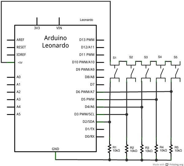
Add four more pushbttons
Repeat the last step, connecting four more pushbuttons to pins 3 through 6.
Follow the same steps as you did in the first Mouse Control lab to read when the pushbutton on pin 2 is pressed. Your code should only print out a message when the button changes state. Similarly, set up a global variable to track whether or not you’re controlling the mouse, called mouseIsActive. Each time the pushbutton on pin 2 is pressed, change the state of this variable from false to true, just like you did in the first mouse control lab.
For more detail: Mouse Control With Pushbuttons
- How many pushbuttons are required for this project?
You need five pushbuttons in total: one connected to pin 2 and four more connected to pins 3 through 6. - Can I test the sketches on an Arduino Uno?
Yes, you can test the sketches on an Uno by commenting out any line that says Mouse.begin() or Mouse.move(). - What is the purpose of the global variable mouseIsActive?
This variable tracks whether or not you are controlling the mouse, changing from false to true when the button on pin 2 is pressed. - How should I connect the pushbutton circuit?
Connect one side of the pushbutton to 5 volts, the other side to a 10-kilohm resistor, and the junction of the pushbutton and resistor to the digital pin. - Does the code print messages immediately upon adding mouse commands?
No, the example does not introduce mouse commands until the end; initially, it prints messages to the serial monitor to indicate expected behavior. - What happens if I run the sketch before testing the serial messages?
The article warns that the sketches will cause the Arduino Leonardo to take control of your mouse, so you must verify serial messages first.
