Summary of Turning PC On with a Knock Using ATtiny45 and a Piezoelectric Sensor
Summary: An ATtiny45 emulates a PS/2 keyboard and sends a keypress when three knocks are detected by a piezoelectric sensor. The knock sensor uses a piezo buzzer with a 1 MΩ resistor; PS/2 (or USB via passive adapter) supplies power and data lines. Optional LED and pullup for RESET provide indicators and stability. The project boots a PC using knock input and can be built on a breadboard or simple PCB.
Parts used in the Turning PC On with a Knock project:
- ATtiny45 (or any ATtiny/ATmega with ≥4kB flash, A/D converter and two timers)
- Piezo buzzer (piezoelectric sensor)
- 1 MΩ resistor (for piezo sensor)
- PS/2 connector or passive USB-PS/2 adapter and USB cable
- Breadboard and hookup wire (or simple PCB for soldering)
- Optional 4.7 kΩ pullup resistor for RESET
- Optional LED
- Optional 330 Ω resistor for LED
Today’s post is something I’ve prepared for a long time. Hardware-wise it’s a simple thing – ATtiny45 emulating a PS/2 device, sending a keypress when three knocks are detected in the attached piezoelectric sensor (or piezo buzzer as they are also called). But if your computer can boot on PS/2 keyboard input and you have your computer stowed somewhere hard to reach (or just want to impress your friends), it’s a pretty neat little gadget! Here’s a video of it in action:
My PC takes a few seconds to put anything on display, but if you look at the bottom right corner, you can see the blue power LEDs light up immediately after the knocks.
What You’ll Need
Hardware-wise this hack is super simple. You’ll need less than $10 in parts and many probably already have these lying around:
- ATtiny45. Actually, any ATtiny or ATmega with 4kB or more flash, A/D converter and two timers will work with small adjustments, and with -Os -DMINIMAL compiler flags also 2kB MCUs (ATtiny2313 doesn’t have a A/D but you can either work around it or use a button)
- Piezo buzzer and 1 Mohm resistor to act as knock sensor
- PS/2 connector, or alternatively a passive USB-PS/2 adapter (I have half a dozen from old keyboards and mice) and USB cable (like the one I used in my V-USB tutorial)
- Breadboard and wire. Alternatively you can solder it on a simple PCB like I eventually did.
- Optionally, a 4k7 ohm pullup resistor for RESET line, and a LED and 330 ohm resistor to indicate state
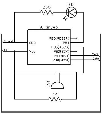
The Schematic and Breadboard Setup
The PS/2 part as discussed in my minimal PS/2 keyboard post doesn’t require any other hardware than the ATtiny. The piezo element uses a 1 Mohm resistor like in the Arduino Knock Sensor tutorial, providing a path for voltage level to get back to zero over time. The LED is connected to PB4.
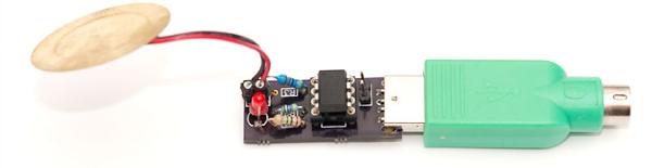
The PS/2 connector also provides power to the device. Instead of soldering a custom PS/2 connector for the project, I took a passive USB-PS/2 adapter I had lying around and used a multimeter to find out which USB pins correspond to the PS/2 ones. Not surprisingly, PS/2 GND and VCC are connected to USB GND and VCC. In my adapters, PS/2 clock was connected to D+ and data to D-. You can see the mnemonic printout I made on that one below, as well as one possible breadboard configuration.
For more detail: Turning PC On with a Knock Using ATtiny45 and a Piezoelectric Sensor
- What microcontroller is used in the project?
The project uses an ATtiny45, or any ATtiny/ATmega with 4kB or more flash, an A/D converter and two timers with small adjustments. - Can I use a different ATtiny or ATmega?
Yes; any ATtiny or ATmega with the stated resources will work, and with -Os -DMINIMAL compiler flags even 2kB MCUs can be adapted. - What sensor detects the knocks?
A piezoelectric buzzer (piezo element) is used as the knock sensor. - What resistor value is used with the piezo sensor?
A 1 MΩ resistor is used to provide a path for the voltage to return to zero over time. - How is the device powered and connected to the PC?
The PS/2 connector provides power and data; a passive USB-PS/2 adapter and USB cable can be used instead. - Do I need extra components for indication or reset stability?
Optionally a 4.7 kΩ pullup resistor for RESET and an LED with a 330 Ω resistor can be added for state indication. - Is a breadboard required?
You can use a breadboard and wires for prototyping or solder the circuit onto a simple PCB. - Does the PS/2 interface require extra hardware beyond the ATtiny?
No; the minimal PS/2 keyboard implementation in the article requires no other hardware beyond the ATtiny.