Summary of Toy Camera Using ESP32 + OV2640 Camera and 3.5″ TFT Touchscreen
This educational project builds a toy camera to teach engineering concepts. It integrates an ESP32-Cam microcontroller, an OV2640 camera module, and a 3.5-inch TFT touchscreen into a custom PCB. The design allows for easy assembly and disassembly, enabling students to learn schematic design, 3D modeling, and programming. Images are captured and stored on an SD card using Arduino libraries like LVGL and LovyanGFX.
Parts used in the Toy Camera Using ESP32 + OV2640 Camera and 3.5" TFT Touchscreen:
- ESP32-Cam development board
- OV2640 camera module
- 3.5-inch TFT touchscreen display
- CH340 USB serial converter
- SD card slot
- PSRAM (if using ESP32-S)
- LoRa module (optional, untested)
- Real Time Clock with coin cell battery backup (untested)
- Custom designed PCB
This project is for educational purposes. I made this for teaching engineering classes for my kids. It helps to describes how the camera works. It consists of three main parts :
- Brain : the microcontroller
- Input : camera module
- Output : TFT display
That parts are need to be easily assembled and disassembled, so our kids can do by themself. This insctructable shows you how we made it from designing the schematic, board layout, 3D model, flashing the MCU and testing the result. All resources such as schematic, gerber files, Arduino source code, and 3D model are available to download. Feel free to use it, you can use for your development board.
Step 1: Ideas and Inspirations
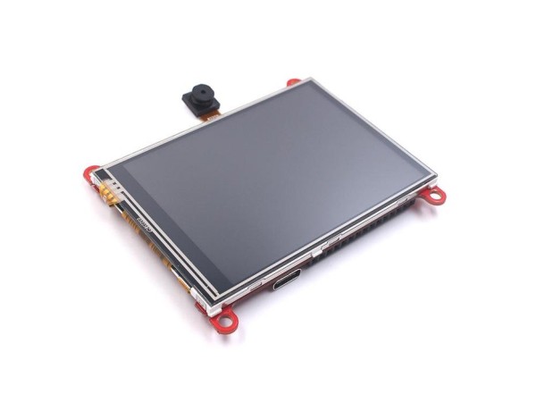
The idea is quite simple, using a cheap development board that includes a camera, ESP32-Cam connected to 3.5″ TFT touchscreen. I also use built in sd-card slot on ESP32-Cam for external memory, so we can store the images on it. All parts need to be combined all together in a single PCB. Thankfully someone has created open-source project that meet with my requirements.
Thank to Makerfabs (ESP32 Touch Camera)
Based-on ESP32 Touch Screen designed by Makerfabs, I made several modifications :
- Using CH340 rather than CP2104, because it cheaper and easy to hand-soldering
- Changes the camera position, I don’t use it for selfie cam
- Changes the SD card slot and USB port posistion in the same side. It will helps when we insert the board to the enclosure
- Add PSRAM if ESP32-S is in use
- Add LoRa module if Camera is not in use (untested)
- Add very accurate Real Time Clock and cell coin battery backup (untested)
Step 2: Designing Schematic and Board Layout
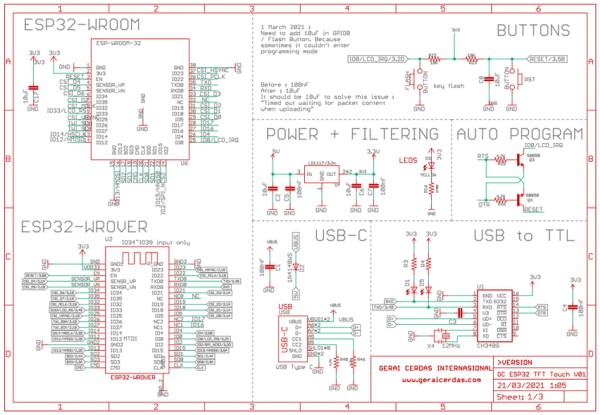
The schematic and board layout are designed in Autodesk Eagle. To generate 3D model of this PCB design, simply click “Fusion 360” in board layout and create a new design. In Fusion 360 I import the components that hasn’t a 3D model.
If you need a 3D model of this PCB, you can download it at my grabcad account : https://grabcad.com/library/esp32-xt-esp32-with-3-5-tft-lcd-and-camera-ov2640-1
Step 3: PCB Assembly
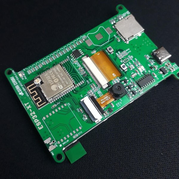
I sent gerber file to PCB manufacturer. After the PCB and all components are arrives, it’s time to assembly all parts by hand-soldering. Actually I already bought an ESP32-Cam and 3.5″ TFT display module, so it just need to desoldering all components in this two modules, and then placed in a new PCB. The rest is adding usb serial converter so it able to upload the firmware without external programmer.
Here is the link if you want to make this PCB : https://github.com/geraicerdas/esp32-xt
Step 4: Programming and Uploading
I use this Arduino libraries :
- LVGL
- LovyanGFX
So make sure this libraries is installed in your Arduino IDE
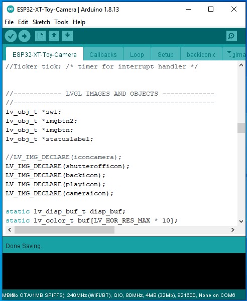
Toy camera Arduino Sketch structures :
- ESP32-XT-Toy-Camera : declaration and functions
- Callbacks : event functions
- Loop : main function
- Setup : setup function
- backicon.c : icon for back button
- bgimage.c : background image
- cameraicon.c : icon for take photo button
- playicon.c : icon for view last photo button
- shutterofficon.c : icon for pressed camera button
Import libraries
#include "bgimage.c"
#include "SPI.h"
#include "SD.h"
#include "FS.h"
#include <esp_camera.h>
#include <lvgl.h>
#include <LovyanGFX.hpp>
Pin definitions
//------ ESP32-XT pin definition --------
//---------------------------------------
#define SPI_MOSI 13
#define SPI_MISO 12
#define SPI_SCK 14

#define LCD_MOSI    SPI_MOSI
#define LCD_MISO    SPI_MISO
#define LCD_SCK     SPI_SCK
#define LCD_CS      15
#define LCD_RST     26
#define LCD_DC      33
#define LCD_BL      -1

#define LCD_WIDTH   320
#define LCD_HEIGHT  480
#define LCD_SPI_HOST HSPI_HOST

// Camera pins
#define PWDN_GPIO_NUM    -1
#define RESET_GPIO_NUM   -1
#define XCLK_GPIO_NUM    32
#define SIOD_GPIO_NUM    26
#define SIOC_GPIO_NUM    27

#define Y9_GPIO_NUM      35
#define Y8_GPIO_NUM      34
#define Y7_GPIO_NUM      39
#define Y6_GPIO_NUM      36
#define Y5_GPIO_NUM      21
#define Y4_GPIO_NUM      19
#define Y3_GPIO_NUM      18
#define Y2_GPIO_NUM      5
#define VSYNC_GPIO_NUM   25
#define HREF_GPIO_NUM    23
#define PCLK_GPIO_NUM    22

#define ARRAY_LENGTH 320 * 240 * 3
#define SCREEN_ROTATION 1


//SPI control for TFT LCD
#define SPI_ON_TFT digitalWrite(LCD_CS, LOW)
#define SPI_OFF_TFT digitalWrite(LCD_CS, HIGH)

//SPI control for SD Card
#define SD_CS 4
#define SPI_ON_SD digitalWrite(SD_CS, LOW)
#define SPI_OFF_SD digitalWrite(SD_CS, HIGH)
Live camera function
void readCamera() {
  fb = NULL;
  fb = esp_camera_fb_get();
    if (stream_flag == 1) {
        tft.pushImage(11, 50, fb->width, fb->height, (lgfx::swap565_t *)fb->buf);
    }
}
Save image to file function
//Save image to SD card
int save_image(fs::FS &fs, uint8_t *rgb) {
    SPI_ON_SD;
    imgname = "/img" + String(img_index) + ".bmp";
    img_index++;

    Serial.println("Image name:" + imgname);

    File f = fs.open(imgname, "w");
    if (!f) {
        Serial.println("Failed to open file for writing");
        return -1;
    }

    f.write(img_rgb888_320_240_head, 54);
    f.write(rgb, 230400); // 3 x 320 x 240

    f.close();

    Serial.println("write successfully");
    SPI_OFF_SD;
    return 0;
}
Display image from file
//Display image from file
int print_img(fs::FS &fs, String filename, int x, int y) {
    SPI_ON_SD;
    Serial.println("filename:" + filename);
    File f = fs.open(filename);
    if (!f) {
        Serial.println("Failed to open file for reading");
        f.close();
        return 0;
    }

    f.seek(54);
    int X = x;
    int Y = y;
    uint8_t RGB[3 * X];
    for (int row = 0; row < Y; row++) {
        f.seek(54 + 3 * X * row);
        f.read(RGB, 3 * X);
        SPI_OFF_SD;
        tft.pushImage(11, 50+row, X, 1, (lgfx::rgb888_t *)RGB);
        SPI_ON_SD;
    }

    f.close();
    SPI_OFF_SD;
    return 0;
}
Please download here for complete source code : https://github.com/geraicerdas/esp32-xt
Source: Toy Camera Using ESP32 + OV2640 Camera and 3.5″ TFT Touchscreen
- What is the main purpose of this project?
This project is for educational purposes to teach engineering classes by describing how a camera works. - Can users assemble and disassemble the device themselves?
Yes, all parts are designed to be easily assembled and disassembled so kids can do it by themselves. - Which microcontroller is used as the brain of the system?
The project uses an ESP32-Cam development board as the microcontroller. - How does the device store captured images?
It uses the built-in SD card slot on the ESP32-Cam to store images on external memory. - Why was the CH340 chip chosen over the CP2104?
The CH340 was chosen because it is cheaper and easier to hand-solder. - What Arduino libraries are required for programming?
The project requires the LVGL and LovyanGFX libraries to be installed in the Arduino IDE. - Does the design include a Real Time Clock?
Yes, it adds a very accurate Real Time Clock with a cell coin battery backup, though it is noted as untested. - Where can users download the source code and resources?
All resources including source code, schematics, and 3D models are available at the provided GitHub and GrabCAD links.