This project is to create an Infrared Remote Control to control the Original Cybot received with the magazine Ultimate Real Robots, started back in 2001.
Reason for making the remote:(a little history)
Before the issue of the parts for the IR handset, Cybot was put into different modes by selecting DIP Switches. (There was no issue with Cybot while this was the case) When the IR Handset was issued, things changed. A processor was upgraded to change the function of the DIP Switches. The DIP Switches where then used to set the channel used by the IR Handset so that more than one Cybot could be used together at the same time. (Up to 16 Cybot could be controlled with the Infrared Controls ) However, when the Infrared-Download-Board was issued, there where problems. Not all the boards where manufactured the same, there where issues that made some not work correctly or not work at all. There was a fix issued but this did not fix all. I was one of the unlucky ones, nothing worked for me from there on, everything relied on the Infrared Handset working.
If you, like me, was one of the unlucky ones that had the same problem, you may wish to dig out your old box of Cybot bits and make this Infrared Controller to control it.
The only thing I could not do is: Voice Control and PC LINK
Step 1: The Remote in Action
I had trouble focusing, I used my old phone to make the video.
Step 2: Cybot
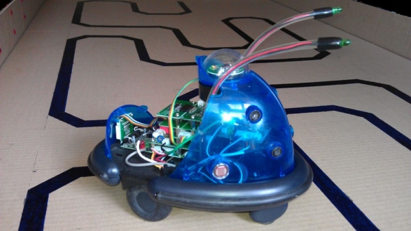
I’m sorry, but unless you have a Cybot, then this is not much use for you.
But if you know anyone that has one:
May be this will resurrect those dormant little fellows, hiding away in those dusty closets 🙂
Step 3: Lets Start. First the Prototype.
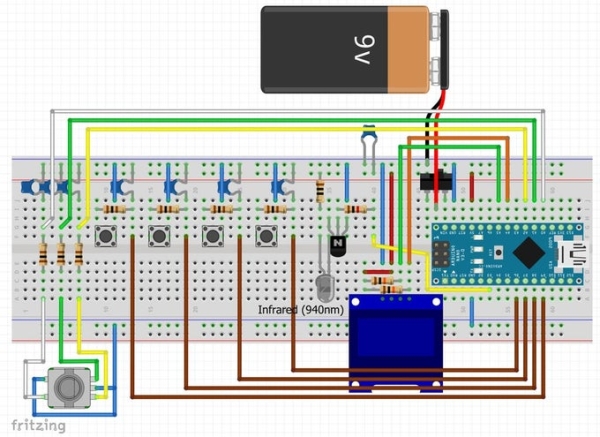
Before making the handset I built a prototype to test thing out and make sure my code worked.
R8 and R9 are pullup resistors for the I2C bus. a lot of people forget to add these to the circuit, but they are required. (one pair per bus, not device)
As a rule of thumb to the resistors are added to the master, but as the Arduino could be used as master or slave and to keep things simple, internal pull are not used in the library.
I have used Internal Pullup Resistors for the Pins connected to the switches. So all Switches are to close to Ground.
The Resistor / Capacitor Pairs R1 to R7, C1 to C7 are to compensate for bounce. (so are not necessary if you want to do a quick test, I recommend them for stability)
Q1 is the driver for the Infrared LED (940nm). This is so full power is used by the LED to transmit the signals. (again if testing next to your Cybot, Q1, C8 and R11 can be removed. Connecting R10 and LED1 in series between Pin D3 and 5v should work)
I created the circuit using Fritzing, so here is the file so you can view it better: Arduino_Handset.zip
Step 4: Program the Arduino
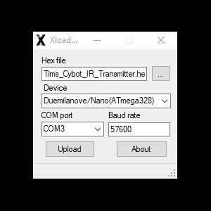
After making the prototype from the circuit above you will need to upload my HEX file to the Arduino NANO.
I use this uploader to do this: XLoader.
I have done a HEX file for the NANO and the UNO. (as far as I know they are both the same)
Arduino NANO: Tims_Cybot_Transmitter_Nano_Atmaga328P_Internal_Pullup.hex
Arduino UNO: Tims_Cybot_Transmitter_Genuino_Uno_Internal_Pullup.hex
For the Built version I use External Pullup Resistors.
Arduino NANO: Tims_Cybot_Transmitter_Nano_Atmaga328P.hex Using External Pullup Resistors.
Arduino UNO: Tims_Cybot_Transmitter_Genuino_Uno.hex Using External Pullup Resistors.
(I don’t know if HEX Files have the bootloader in them, but I did these HEX Files with it configured to Old Bootloader for the NANO)
XLoader is an easy program to use, you don’t need to install it, it is a standalone program that runs from wherever yo put it. You tell it where the file is and tell it where to send it.(the port your NANO is plugged into)
Step 5: Next Step Is to Make a Functional Usable Handset.
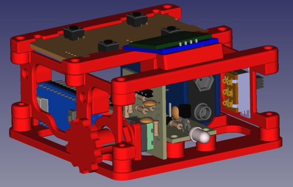
Rather than make one circuit board and mount everything to the one board, I have decided to make this project modular.
By making it modular, some modules may be found on the internet.
Also, you will see from the sketch, I like show all the inner workings of my projects 🙂
Step 6: List of Components / Modules:
Step 7: Arduino NANO
The chip needs to be ATmega328 (If you are using China Clones)
This program uses 90% of both SRAM and EEPROM
Read more: Tim’s Cybot Arduino NANO Remote Control