Summary of TiDiGino Contest using arduino
TiDiGino is an Arduino-based GSM remote control project challenging developers to write firmware supporting multiple legacy functions. It utilizes an ATMEGA2560 chip and a SIM900 module, requiring custom pin configuration files for compatibility with existing shields. The contest invites submissions via email with specific hardware and experience requirements, offering devices and prizes to selected candidates.
Parts used in the TiDiGino:
- ATMEGA2560 chip
- SIM900 GSM module
- Arduino Mega 2560 board (modified)
- DS18B20 temperature sensor
- External power supply (12V 1A)
- GSM TDGINO library
- Dallas Temperature Control Library
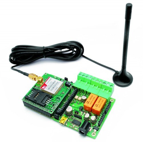
The project TiDiGino
We developed a new GSM remote control called TiDiGino. The name recalls the initials (TDGxx) of our previous GSM remote control and is also based on the Arduino project. All the details of this circuit can be found below, but no the sketch, because this is your assignment.
The contest
You have to write the firmware for this project. The device must perform all the functions of the past GSM remote control: TDG133 (remote 2IN 2 OUT), TDG134 (gate remote control), TDG139 (GSM thermostat) and TDG140 (DTMF remote control). Before you start thinking about the new firmware it is therefore necessary to understand what are the functions performed by various GSM remote control proposed in the past and understand how you can get anything from a single circuit: the TiDiGino!
 How to participate
To write the sketch you must have a TiDiGino device. Don’t worry, we’ll give away 10 TiDiGino’s to candidates chosen by the community. If you want to engage in firmware developing and get one GSM remote control, you have to send an your professional or academic experience and send us at least one project you made with the Arduino platform. We’ll post the projects in this blog to showcase your works and give the opportunity to pick the 10 candidates who will receive the remote control for free.
Send your projects, experience and also idea until the end of August 2011 using the contact form. In September we’ll nominate the candidates with most votes and we’ll send them the GSM remote control TiDiGino. Warning: our remote control does not include the SIM card. By the end of September, the best firmware wins a handheld oscilloscope HPS50 by Velleman. Obviously, anyone can participate in the Contest by sending the firmware developed.
Send now your request for participation using the contact form (registration are closed) Thank you.
You can attach a zip file (max. 5 MB) containing:
– Your personal details and a brief description of your experience (max. 1 page);
– A complete project made with Arduino, including a description of the circuit, the circuit diagram, PCB (in the case of shield), the sketch and one or more photos in jpg format.
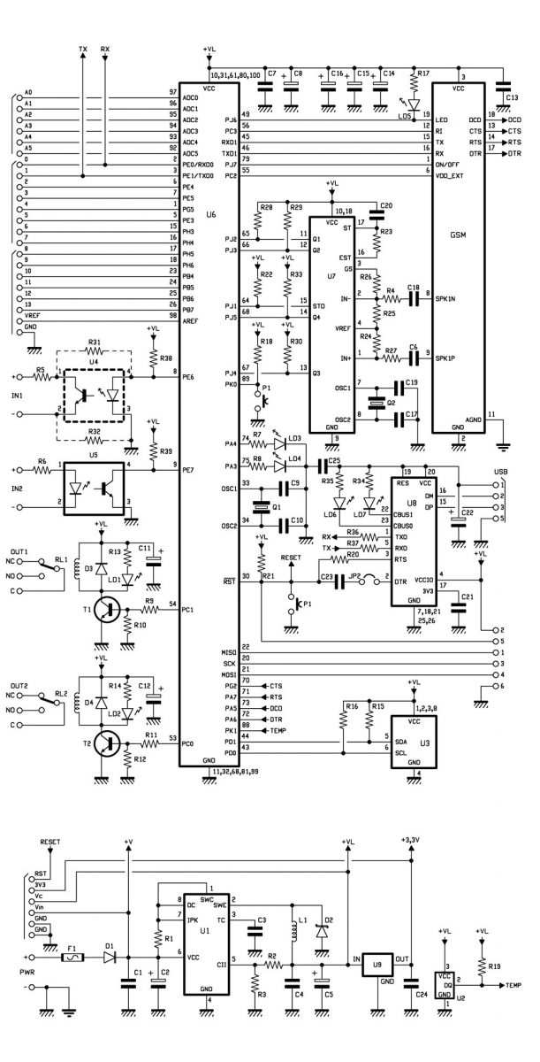
The Projects: GSM remote control TiDiGino
TiDiGino is based on a ATMEGA2560 chip, some of his pins are used to manage the GSM module, these ports are not used from the original Arduino MEGA 2560, so for this reason it is necessary replace the file pins_arduino.c located under the IDE installation folder (eg C: \ Program Files \ arduino-0022 \ hardware \ arduino \ cores \ arduino) with the file content in this folder: pins_arduino.zip
This allow to use any additional shield. Therefore you can use sketches already made for the original Arduino Board to control a particular shield with TiDiGino.
The file GSM_TDGINO.zip contains the library to manage the GSM of TDGINO. This library is derived from one developed by HWKitchen but has been adapted to our hardware. In particular, we use the second serial of the ATMEGA2560 to manage the GSM module SIM900. Decompressing the zip in the folder of the Arduino libraries (eg C: \Program Files \ arduino-0022 \ libraries) the library is immediately usable.
The library is similar to the GSM SHIELD library. And for this shield Marco Martines developed the GPRS functions that you can implement in this library.
By copying the library, are automatically installed the examples that we have developed to manage the various devices. In order to test these examples you need to connect to the USB port TiDiGino and provide an external power supply of about 12V 1A. This creates a virtual COM will be used to program the remote control. Select Board “Arduino Mega 2560″ and from the menu File-> Examples-> GSM_TDGINO choose the example you want to load on the telecontrol.
TDGINO CALL
This sketch allows you to understand how the library control the GSM module. The status of the call, or if there is a call in progress, or no incoming call is send to the serial port. The sketch reads the first 10 phone numbers found on the SIM and if a SMS arrives it send the data on the serial port.
|
1
2
3
4
5
6
7
8
9
10
11
12
13
14
15
16
17
18
19
20
21
22
23
24
25
26
27
28
29
30
31
32
33
34
35
36
37
38
39
40
41
42
43
44
45
46
47
48
49
50
51
52
53
54
55
56
57
58
59
60
61
62
63
64
65
66
67
68
69
70
71
72
73
74
75
76
77
78
79
80
81
82
83
84
85
86
87
88
89
90
91
92
93
94
95
96
97
98
99
100
101
102
103
104
105
106
107
108
109
110
111
112
113
114
115
116
117
118
119
120
121
122
123
124
125
126
127
128
129
130
131
132
133
134
135
136
137
138
139
140
141
142
143
144
145
146
147
148
149
150
151
152
153
154
155
156
157
158
159
160
161
162
163
164
165
166
167
168
169
170
171
172
173
174
175
176
177
178
179
180
181
182
183
184
185
186
187
188
189
190
191
192
193
194
195
196
197
198
199
200
201
|
/* TDGino exampleSketch to test the call function created 2011 by Boris Landoni This example code is in the public domain. */#include <GSM.h>//for enable disable debug rem or not the string #define DEBUG_PRINT// definition of instance of GSM classGSM gsm;// Set pin numbers:const int powergsm = 77;const int ctsgsm = 39;const int rtsgsm = 29;const int dcdgsm = 27;const int dtrgsm = 28;const int reset = 35;const int ring = 34;const int ld1 = 25;const int ld2 = 26;const int stato = 76;const int rele1 = 36;const int rele2 = 37;const int sda = 20;const int scl = 21;const int in1 = 84;const int in2 = 83;const int stddtmf = 14;const int q1dtmf = 72;const int q2dtmf = 73;const int q3dtmf = 74;const int q4dtmf = 75;const int puls = 62;const int sonda = 63;void setup() { // set the digital pin as output: pinMode(powergsm, OUTPUT); pinMode(rtsgsm, OUTPUT); pinMode(dtrgsm, OUTPUT); pinMode(reset, OUTPUT); pinMode(ld1, OUTPUT); pinMode(ld2, OUTPUT); pinMode(rele1, OUTPUT); pinMode(rele2, OUTPUT); pinMode(sda, OUTPUT); pinMode(scl, OUTPUT); // set the digital pin as input: pinMode(ctsgsm, INPUT); pinMode(dcdgsm, INPUT); pinMode(ring, INPUT); pinMode(stato, INPUT); pinMode(in1, INPUT); pinMode(in2, INPUT); pinMode(stddtmf, INPUT); pinMode(q1dtmf, INPUT); pinMode(q2dtmf, INPUT); pinMode(q3dtmf, INPUT); pinMode(q4dtmf, INPUT); pinMode(puls, INPUT); pinMode(sonda, INPUT); // start serial port at 9600 bps: Serial.begin(9600); //Serial1.begin(115200); Serial.println("system startup"); //gsm.InitSerLine(115200); //initialize serial 1 gsm.TurnOn(115200); //module power on gsm.InitParam(PARAM_SET_1);//configure the module gsm.Echo(1); //enable AT echo}void loop(){ int response=0; char phone_num[20]; // array for the phone number string char string[160]; // if we get a valid byte, read analog ins: if (digitalRead(in1) == 0 ) { digitalWrite(ld1,HIGH); digitalWrite(rele1,HIGH); } else { digitalWrite(ld1,LOW); digitalWrite(rele1,LOW); } if (digitalRead(in2) == 0 ) { digitalWrite(ld2,HIGH); digitalWrite(rele2,HIGH); } else { digitalWrite(ld2,LOW); digitalWrite(rele2,LOW); } if (digitalRead(puls) == 0 ) { Serial.println("pulsante premuto"); digitalWrite(rele1,HIGH); delay(2000); digitalWrite(rele2,HIGH); delay(2000); digitalWrite(rele1,LOW); delay(2000); digitalWrite(rele2,LOW); delay(2000); response=gsm.DeleteSMS(1); Serial.print("Response del "); Serial.println(response); for (int i=0; i<=10; i++) { if (1 == gsm.GetPhoneNumber(i, phone_num)) { // valid phone number on SIM pos. #1 // phone number string is copied to the phone_num array #ifdef DEBUG_PRINT sprintf(string, "DEBUG position %i phone number:", i); gsm.DebugPrint(string, 0); gsm.DebugPrint(phone_num, 1); #endif } else { // there is not valid phone number on the SIM pos.#1 #ifdef DEBUG_PRINT gsm.DebugPrint("DEBUG there is no phone number", 1); #endif } } response=gsm.IsSMSPresent(SMS_UNREAD); Serial.print("Response UNREAD "); Serial.println(response); if (response) { gsm.GetSMS(response, phone_num, string, 160); #ifdef DEBUG_PRINT gsm.DebugPrint("Numero ",0); gsm.DebugPrint(phone_num ,0); gsm.DebugPrint("\r\n Testo ",0); gsm.DebugPrint(string ,0); #endif } delay (1000); response=gsm.IsSMSPresent(SMS_READ); Serial.print("Response READ "); Serial.println(response); if (response) { gsm.GetSMS(response, phone_num, string, 160); #ifdef DEBUG_PRINT gsm.DebugPrint("Numero ",0); gsm.DebugPrint(phone_num ,0); gsm.DebugPrint("\r\n Testo ",0); gsm.DebugPrint(string ,0); #endif } delay (1000); response=gsm.IsSMSPresent(SMS_ALL); Serial.print("Response ALL "); Serial.println(response); if (response) { response=gsm.GetAuthorizedSMS(2, phone_num, string, 160,1,9); #ifdef DEBUG_PRINT gsm.DebugPrint("Numero ",0); gsm.DebugPrint(phone_num ,0); gsm.DebugPrint("\r\n Testo ",0); gsm.DebugPrint(string ,0); gsm.DebugPrint("\r\n Auth ",0); gsm.DebugPrint(response,0); #endif } delay (1000); //gsm.HangUp(); } response=gsm.CallStatus(); Serial.print("Response "); Serial.println(response); delay (2000);} |
 TDGINO TEMP
This firmware allows you to test the temperature sensor DS18B20. For communication with the sensor must have the library available from:
http://www.milesburton.com/Dallas_Temperature_Control_Library
Once loaded in the sketch TiDiGino, pressing the button will send an SMS containing the temperature at the specified number. Moreover, during a remote call, the sistem answer and pressing the keypad of your phone you can test the DTMF section.
For more detail: TiDiGino Contest
- What chip powers the TiDiGino device?
The device is based on an ATMEGA2560 chip. - How do you manage the GSM module on this circuit?
The second serial port of the ATMEGA2560 manages the SIM900 module. - Can I use original Arduino sketches with TiDiGino?
Yes, by replacing the pins_arduino.c file to allow usage of any additional shield. - What external power supply is required to test examples?
You need to provide an external power supply of about 12V 1A. - Which board setting should be selected in the IDE?
Select Board Arduino Mega 2560 in the menu. - Does the provided remote control include a SIM card?
No, the remote control does not include the SIM card. - What prize is awarded to the best firmware winner?
The winner receives a handheld oscilloscope HPS50 by Velleman. - How can participants apply for the contest?
Participants must send their experience and projects via the contact form.