Summary of The Desktop Device – a Customizable Desktop Assistant
The Desktop Device is a small customizable desktop assistant built with an ESP32, a 2.2" SPI display, buttons, and optional components. The creator breadboarded the circuit, tested functionality, then designed a custom PCB in EasyEDA and soldered the final hardware into a stand or case. The project was done for a Berry College class and includes parts, wiring guidance, and optional enclosure/3D-printing notes.
Parts used in the Desktop Device-a-Customizable-Desktop-Assistant:
- ESP32 development board ($11 link)
- Micro USB cable ($7 link)
- HiLetgo 2.2" 240x320 SPI display ($17 link)
- Jumper wires ($6.50 link)
- 10 µF capacitor (optional, from capacitor kit)
- Capacitor kit ($15.50 link)
- 10k Ohm resistors (from resistor kit)
- Resistor kit ($9 link)
- Buttons (various, from button kit)
- Button kit ($17 link)
- 1/16" acrylic for stand (or other material) ($10 link)
- Spacer screws for mounting the board ($12 link)
- XYZ 3D printer (optional, for enclosure)
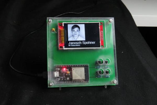
In this post, we will learn The-Desktop-Device-a-Customizable-Desktop-Assistant: The Desktop Device is a small personal desktop assistant that can display various information downloaded from the internet. This device was designed and built by me for the CRT 420 – Special Topics class at Berry College which is lead by Instructor Zane Cochran.
This instructable will go into detail about how to build your own device similar to this one. In the video that I linked, the more visually appealing steps as well as some grade A commentary from me show the process of the device being built. I’m relatively new to YouTube but I am trying to make some interesting DIY / automotive content so feel free to check it out and let me know what you think I could improve on! Also if you want to check out some of my other Instructables, you can do so by clicking on my profile.
Below are the items and software that are used to create the desktop device (The Amazon links are affiliate links which support me when you purchase items through them, at no extra cost to you)
Much like SlouchyBoard (https://www.instructables.com/id/SlouchyBoard-an-A…), we started out by Breadboarding this circuit to make sure everything worked before we soldered it into a Printed Circuit Board (PCB). These are the breadboarding components that I used to make sure everything works.
$11 ESP32: https://amzn.to/2HfT26Y
$7 Micro USB: https://amzn.to/2PXntSb
$17 Screen(HiLetgo 2.2″ Display 240×320): https://amzn.to/2LNc0Gu
$6.50 Jumper Wires: https://amzn.to/2ViOfFm
(Not required, but we used a 10microFahrad Capacitor to make the screen run much better)
$15.50 Capacitor kit: https://amzn.to/2LDNcR4
10k Ohm resistors (If you ever bought an Arduino kit you probably already have these)
$9 Resistor Kit: https://amzn.to/2vVTwbL
Buttons (again, you probably have some, just make sure your PCB has the correct button!):
$17 Button kit (in case you want some other button choices):https://amzn.to/2E4Gu0j
$10 Acrylic (I used some 1/16″ acrylic to make my stand, however, anything could be used): https://amzn.to/30eFyQf
$12 Spacer screws (used to attach the board to the case): https://amzn.to/2Yq5tTn
I originally wanted to 3D print a case but ended up running out of time. In the lab, we use the XYZ 3D printers which make for a good starting printer: https://amzn.to/2JAyasy
After testing all components and doing some basic programming tests, we went onto EasyEDA (https://easyeda.com/) to make the custom PCB board. Once that was done we moved all of those components over to the PCB and soldered them into place. The following steps will go into detail for the build.
The total price of this project depends a lot on what you decide to make for yourself, what components you already have and/or chose to use.
Steps for The Desktop Device – a Customizable Desktop Assistant:
Step 1: Breadboarding
To begin, you want to start by wiring up all your components in a breadboard according to the circuit schematic as shown. You should wire up the screen exactly as shown in the schematic as those pins work with the screen’s library, however, the buttons don’t matter as much and you can do whatever you want.
You don’t have to use 4 buttons or any buttons at all, you could use a joystick if you really wanted to. Below are the pins that I used. Note that these are the pins that are used in programming and not the physical pins. For example, the CS pin is connected to pin 22, which is actually the third pin from the top right when viewed from the schematic.
There are a few different versions of the ESP-32 out there so some of the pins may not be exactly the same as shown in this project. If yours is different try to find a pinout diagram for your version.
- What is the Desktop Device?
The Desktop Device is a small personal desktop assistant that can display various information downloaded from the internet. - What microcontroller is used in the project?
The project uses an ESP32 development board. - What display is used for the Desktop Device?
The project uses a HiLetgo 2.2" 240x320 SPI display. - Do I need buttons for the device?
Buttons are optional; the creator used four but notes you can use fewer, none, or a joystick. - Is breadboarding necessary before making the PCB?
Yes, the creator breadboarded the circuit to verify operation before designing the PCB in EasyEDA. - Was a custom PCB used in the final build?
Yes, after testing, the components were moved to a custom PCB designed in EasyEDA and soldered in place. - Is a capacitor required for the display?
A 10 microfarad capacitor was used to make the screen run much better but it is not strictly required. - Can I 3D print a case for the device?
Yes, a 3D printed case was considered; the creator planned to but ran out of time and used other stand options instead. - Where was this project created?
The device was designed and built for the CRT 420 Special Topics class at Berry College led by Instructor Zane Cochran.