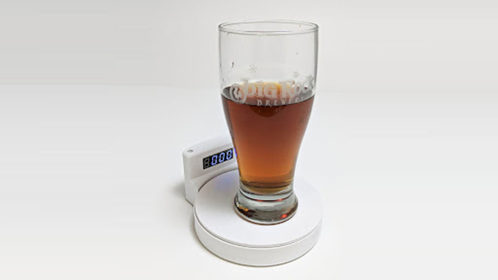
Summary of The Chug-O-Meter
This article details a DIY Chug-O-Meter project designed to track drinking time while protecting electronics from spills. The team improved upon an existing circuit.io design by replacing force sensors with durable switches and housing the components in a custom 3D-printed ABS enclosure. The device utilizes a SparkFun 7-Segment Serial Display, which functions as an Arduino, programmed via an FTDI adapter to count the duration between placing a full glass and removing it.
Parts used in the Chug-O-Meter:
- DC-DC Boost Converter Power Supply Module
- CR2032 Coil Cell Holder
- CR2032 Lithium Battery
- Power Switch
- Snap Lever Switches (3x)
- 7-Segment Serial Display
- #2-56 Thread Forming Screws
- M3 x 10mm Machine Screws
- 3D Printer Filament (ABS+ White)
- 10k Resistor
- 0.1uF Capacitor
- Groovy Noodle Wire
- Double sided tape or hot glue
- TTLyFTDI USB-to-TTL Adapter
- Male Strip pins 6 pos
Isn’t it nice when you can hit two birds with one stone?
That’s exactly what we’ve done as we approach both Arduino Day and Saint Patrick’s Day with our version of the Chug-O-Meter!
We absolutely loved what the circuit.io team did with their Chug Meter but thought that we could add more to its survivability while surrounded by inebriated merrymakers. To do this we changed the force sensor to regular switches, created a 3D printed abs enclosure, and then placed the electronics inside the enclosure to keep them away from accidental spills and splashes.
Step 1: Gathering the Parts
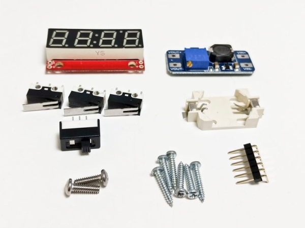
Parts
It can be awesome working at an electronics company when you want to design and build a project. For the Chug-O-Meter, we dived into our stock and found several components that will fit the build.
· 1x DC-DC Boost Converter Power Supply Module (40408)
· 1x CR2032 Coil Cell Holder (50484)
· 1x CR2032 Lithium Battery (BattC2032)
· 1x Power Switch (SWT1A)
· 3x Snap Lever Switch (SWT9)
· 1x 7-Segment Serial Display (50424)
· 6x #2-56 1/2” Thread Forming Screw (Not carried as Solarbotics)
· 2x M3 x 10mm Machine Screw (M3x10-PPH)
· 1x Roll of your favorite 3D Printer Filament. We used eSun ABS+ White (60801)
· 1x 10k Resistor (R10k)
· 1x 0.1uF Capacitor (CP0.1uF)
· 2x colors of Groovy Noodle Wire (15060)
· 1x double sided tape or hot glue
Tools
One thing you may have noticed in the parts list is that we haven’t included an Arduino! Weird, huh? Well that’s because of SparkFun’s 7-Segment Serial Display is actually an Arduino in and of itself! Because of this, we’ve overwritten the code used to control the display with regular Arduino code that will control the Chug-O-Meter instead. To do this though, we will need a serial programmer and interface header to do the job.
· 1x TTLyFTDI USB-to-TTL Adapter (39240)
· 1x Male Strip pins 6 pos (MPin6RA)
Note: During the build process, do not solder the Male Strip Pins to the 7-Segment display as there isn’t enough clearance in the enclosure to allow for it when inserting the display!
Files
3D Print Files: https://www.thingiverse.com/thing:3705513
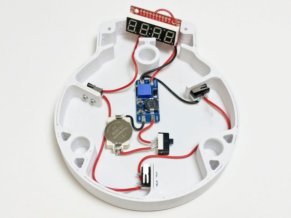
Step 2: Starting the Build
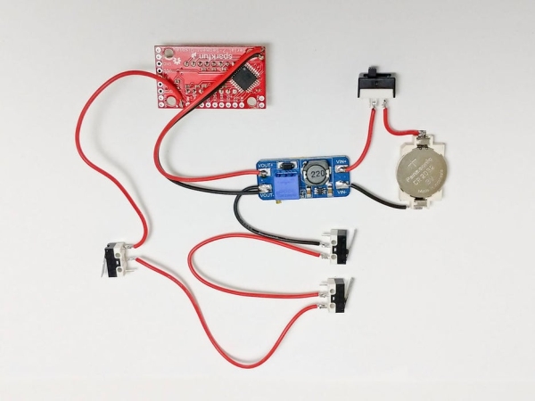
To start, we are going to solder together the circuit as shown in the image above. This will allow us to power the circuit, turn it off and on, it senses when a drink is placed or removed, and then display the time on the 7-segment display.
Step 3: Programming the Display
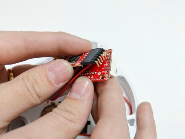
Now that we have the circuit together, it’s time to add the
code to the display. The picture above depicts how the header is inserted into the 7-segment display, and instead of soldering, we use the tried and true method of “add some force to hold it in place while you program”! However, before we can program our device, we need to do a few simple things to the Arduino environment to make it 7-segment ready.
1. Download and install the latest version of the Arduino IDE (Arduino IDE)
2. Open Arduino and navigate to File > Preferences and then add the following line to the “Additional Board Manager URLs:” (if you already have the text here, just add a “,” to the end of the existing text and then paste the following line after it)
3. Press the okay button for the preferences menu and then navigate to Tools > Board: > Boards Manager…
4. In the “filter your search…” bar, type “Sparkfun avr”
4. Click the install button from the image above, making sure that you install the most recent version which in our case was 1.1.12.
With the proper board now installed, programming the SparkFun 7-segment is only a few simple steps!
1. Copy the code into a new Arduino project or download our zip file for the project and extract and open the
.ino file.
2. Next Select the appropriate board by going Tools > Boards: >Sparkfun Serial 7-Segment Display
3. Select the Port that the FTDI programmer is connected to by going Tools > Port > COM X
4. Finally, while holding the FTDI programmer to the pins on the 7-segment display, press the upload button to program the display with the Chug-O-Meter code.
Fixing the Whoopsie
During the build process of this project, we realized too late that the analog pin that the buttons used to sense the addition/removal of a drink does not have an internal pull-up resistor or debouncing capacitor. To fix this issue, we went ahead and added one ourselves to fix this issue, we recommend that you do the same!
Step 4: Finishing the Build
Now that the display has been programmed and the circuit is complete, it’s time to add the electronics to the enclosure.
1. Double-sided tape or hot glue the electronics as shown so that none of them extend past the top of the enclosure. This will keep them in place and stop any collisions with the sensing switches and plate
2. Screw in the switches as shown using the #2-56 thread forming screws. If you don’t have these, you can also use hot glue, but they won’t be near as robust.
3. Insert the display into the cavity of the display holder and use gravity to wiggle it into dropping into place so that the display is flush with the outside of the enclosure. Since we were kind of running out of time for elegant solutions, we used some ESD-Safe foam to hold it in place, but you could also use paper or anything else that is non-metallic.
4. Finally, use the #4-40 screws to mount the display holder onto the enclosure. You can now flick the switch to turn on the circuit and add the sensing plate to cover everything up!
Step 5: Using the Chug-O-Meter
The Chug-O-Meter has been programmed to make operation a breeze! Turn it on, place down a full glass of whatever liquid you prefer, remove the glass to start the count and start chugging! Once you’ve finished, place the empty glass on the sensing plate to stop the timer. To reset the device, remove the empty cup and place a fresh, full cup onto the plate. happy chugging!
If you like building our kit, send us a photo of your build via email at [email protected] and we’ll feature it!
For other updates and guides, go to Solarbotics and be sure to follow us on Facebook and Instagram.
Step 6: Arduino Firmware Files
Make sure to download the supporting library for Sparkfuns Seven Segment display here:
https://github.com/sparkfun/SevSeg
Source: The Chug-O-Meter
- How does the Chug-O-Meter protect its electronics?
The team replaced the original force sensor with regular switches and placed all electronics inside a 3D printed ABS enclosure to prevent damage from spills. - What component serves as the microcontroller for this project?
The SparkFun 7-Segment Serial Display acts as an Arduino in itself, requiring overwritten code to control the meter. - Can I solder the male strip pins to the display before programming?
No, you should not solder the pins because there is not enough clearance in the enclosure to insert the display afterward. - How do I install the necessary board manager for the Arduino IDE?
Add the Sparkfun index URL to the Additional Board Manager URLs in preferences and then install the Sparkfun avr package via the Boards Manager. - Why was a capacitor added to the circuit during the build?
A capacitor was added because the analog pin used for sensing drinks lacked an internal pull-up resistor or debouncing capability. - How do you secure the electronics inside the enclosure?
You can use double-sided tape or hot glue to hold the electronics so they do not extend past the top of the enclosure. - What is the best way to mount the display holder to the enclosure?
Use #4-40 screws to mount the display holder onto the enclosure after inserting the display into the cavity. - How do you reset the device after finishing a drink?
Remove the empty cup and place a fresh, full cup onto the plate to reset the timer.