During my high-school sophomore year, the 3rd floor of our house lighted on fire due to a short circuit. Fortunately, my family was away on vacation for Christmas. But if we were home, wouldn’t it be crucial to tell the direction of fire quickly so that we know the direction to evacuate?
Consider another situation. You really hope to learn Arduino programming, which enables you to build both functional and decorative things. First, you need to get past the basics of the wiring and the programming language. But after you get past this hurdle, whenever you hope to create with some complexity, tutorials online often consist of “replicate this wiring over here; then copy and paste the code into Arduino”. Do you hope to learn the “why” under each part of a tutorial? Do you hope to be able to alter parts of a tutorial to fit with your own needs?
If you have answered “yes” to any of the three questions above, then you are at the right place. In this tutorial, we will be going step-by-step from 0 to 100%. By the end of this tutorial, you will understand the underlying functions and challenges. You will know the different skills, such as integrating sensors, programming RGB colors, and using arrays, that can be used elsewhere. I gradually learned those skills as a newbie myself, so I understand your potential challenges and I fully trust that you can do this! Have fun building!
Step 1: Potential Challenges and Safety Hazards
This tutorial does not require complex skills of Arduino programming, as small steps will be explained to lead you up to the final product. However, there is a tiny bit of soldering involved with this neopixel ring here so please be careful when you are on this step! It is not complex though: drop the solder and attach the wire.
Step 2: Let’s Go Over Our Materials First!
Required materials are the materials necessary to complete the final product.
Optional materials are the materials only necessary to complete mini-activities.
Required materials:
-1 Arduino board (preferably Arduino Uno, to store your program)
-1 Base Shield V2 (this project requires a bunch of sensors, and this base shield attached to your Arduino keeps it tidy!)
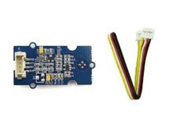
-7 MLX90615 infrared temperature sensors (infrared temperature sensors are capable at telling differences in temperature even when they are not spaced far apart; if you are using smoke sensors to detect fire, you would need to place them 15m apart!)
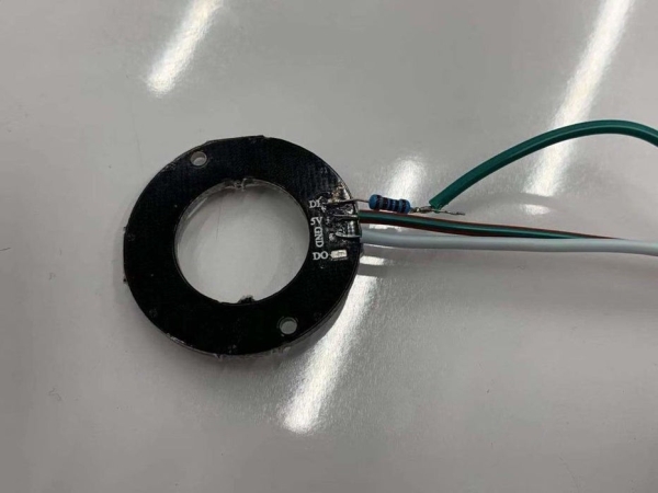
-1 neopixel ring
-Arduino software on computer (this can be downloaded for free on https://www.arduino.cc/en/main/software)
-1 5V resistor (which will be attached to the neopixel ring)
-7 Grove 4 pin connector cables
-Arduino Breadboard
-Soldering tools (to solder wires onto the neopixel ring)
Optional materials:
-3 RGB led lights
-3 Arduino digital capacitive touch sensors
-1 Arduino breadboard
-20+ M-M wires (M means male; wires with pins pointing out on both sides)
Step 3: Obtaining Temperature With the Infrared Temperature Sensors
Before we tangle ourselves with using lights, we will first be learning how to obtain temperature from an infrared temperature sensor. This part of the tutorial is adapted from the webpage (http://wiki.seeedstudio.com/Grove-Digital_Infrared_Temperature_Sensor/) On this site, you will be able to download the demo code and incorporate it into your Arduino library. This is necessary because the demo code contains a set of codes that should be included to make the sensors function properly. The code for this inclusion is
#include “MLX90615.h”
SoftI2cMaster i2c_1(sda_1, scl_1);
MLX90615 mlx90615_1(DEVICE_ADDR, &i2c_1);
If you are doing multiple devices (as we are going to later on), you paste the last two lines of code again and change the number to 2 or whatever the number the sensor is given.
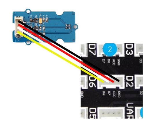
Then, the SDA and SCL ports need to be defined. SCL is the clock line, which is used to synchronize all data transfers. SDA is the data line. On the backside of the temperature sensor, you can see SDA and SCL. When you attach the SDA and SCL cords, they correspond directly to the Dx on the base shield. In this diagram, SCL is connected to D6 and SDA is connected to D7, so on code it is:
byte sda_1 = 7;
byte scl_1 = 6;
Note: It is totally okay if you later write byte sda_2 = 6 because SDA & SCL are separately defined!
Then we will be coding for void set up and void loop in the software. The void set up only runs once at the start of the program (because it is a “set up”!) while the loop will be run again and again.
void setup()
{Serial.begin(9600);
Serial.println(“Setup…”);}
The first line means to open the serial port and set data rate to 9600 bytes per second (bps).
The second line means to print and show your obtained data on the serial monitor.
There are a few rules that you should be aware of here:
At the end of a line you must use a semicolon, or there will be a compiler error.
Curly braces are used for telling the beginning and end of a statement, and an opening brace must be followed by a closing brace.
For the loop of getting the temperature, the code is:
void loop ()
{Serial.print(“Object temperature: “); Serial.println(mlx90615_1.getTemperature(MLX90615_OBJECT_TEMPERATURE));
Serial.print(“Ambient temperature: “); Serial.println(mlx90615_1.getTemperature(MLX90615_AMBIENT_TEMPERATURE));
delay(1000);}
This function allows you to print two things “Object temperature” and “Ambient temperature” with the mlx90615_1 sensor defined previously. By changing the delay time (currently 1 second or 1000 microseconds) you can play with the time intervals you want your sensors to wait before obtaining new temperature data.
This is the end of this set of code, and you can upload through pressing the green arrow (called “Upload) in the Arduino software. If the code does not upload properly, go to Tools – Port and check if you are connected to the right port. (If you are connected by USB, you would see a separate usb port than the normal bluetooth port) If you don’t see the usb port try reattaching the usb cord or restarting your computer.
Once you wire up the sensor to D6 & D7 (on the big D6 port) and upload the code above, you will be able to see temperature data in the Arduino software through Tools -> Serial Monitor.
Step 4: Output? Input?
We want to make temperature change the color of a light. Therefore, the temperature is the input and the light’s color is the output. On step 3 we went over how to obtain the input, so how do you use that information to affect the output?
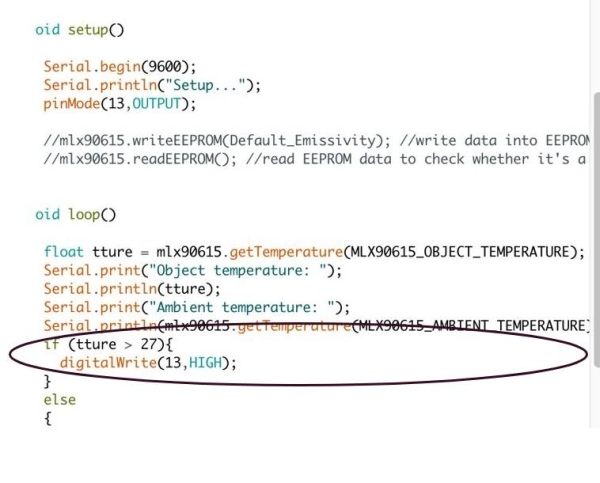
In addition to our previous code, we can write up a command to turn pin 13 ON when a certain condition is reached. In the setup, you set 13 as output through pinMode (13, OUTPUT).
Then, in the loop section, you use the float function, which obtains data that is in decimal point format and is constantly changing. In this example, we name the object temperature as “tture” and add it to the previous code.
float tture = mlx90615.getTemperature(MLX90615_OBJECT_TEMPERATURE);
Then, after the same codes previously for obtaining temperature from the sensors, we command the pin 13 to act according to the data given. This time let’s try a simple one: pin 13 turns on when temperature of the sensor exceeds 27, and turns off when the temperature is below 27. We use digital write to control the pin’s behavior.
if (true > 27){
digitalWrite(13,HIGH);
}
else{
digitalWrite(13,LOW);
}
You can check this through putting your hand over the sensor. If pin 13 turns on, you would be able to see a small yellow light emerging.
Step 5: Programming RGB
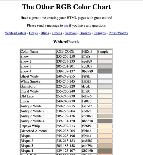
You may be wondering, how could we create a range of colors with arduino? This can be achieved through programming a RGB light, which mixes red, green and blue values in different degrees to form various colors. RGB codes are given in the form (red value, green value, blue value). The maximum value given is 255. (255, 0,0) is red, (0,255,0) is green and (0,0,255). You can visit this link for a thorough color chart to create whichever colors you want: http://www.tayloredmktg.com/rgb/
On a standard Arduino RGB light, you can see how there are four cords, red, blue, green and ground. Similarly to the previous drill, you can define 9 as output red, 11 as output green and 12 as output blue. Then in the loop, instead of using digitalWrite you use analogWrite, in the format:
analogWrite (9, 200);
analogWrite (11, 100);
analogWrite (12, 100);
Step 6: Step 6: How to Use a Range of Values: Changing One RGB Light With One Sensor
Let’s do a mini-activity with the breadboard and the RGB light! The final product of this mini-activity would be a RGB light that changes from purple to red depending on the temperature around the sensor.
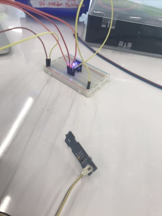
The wiring would consist of using the breadboard. You can see that on the left, there are two columns: negative and positive (indicated by the sign). On your Arduino you can see GND (ground) and 5V (power source). Plug one wire between a GND port and the end of the negative column. Plug one wire between a 5V port and the end of the positive column. Then, connect one wire between the negative and a row where the ground of the RGB light is in (on the two sides the columns are electrically connected, in the middle the rows are electrically connected, see the purple lines on picture 5). Then, the columns where the Red, Green and Blue pins are in are connected with pins on the Arduino via wires. In the following code, pin 10 on Arduino is connected with red, 11 with green and 12 with blue.
After we are done with the wiring, let’s get to the coding.
#include “MLX90615.h”
byte scl_1 = 2;
byte sda_1 = 3;
int ledPin1 = 10; // red
int ledPin2 = 11; // green
int ledPin3 = 12; //blue
We define the 3 pins as 11, 12 and 13.
SoftI2cMaster i2c_1(sda_1, scl_1); MLX90615 mlx90615_1(DEVICE_ADDR, &i2c_1);
void setup() {
Serial.begin(9600);
Serial.println(“Setup…”);
pinMode(ledPin1, OUTPUT);
pinMode(ledPin2, OUTPUT);
pinMode(ledPin3, OUTPUT);
We set the three pins as output; other parts are explained previously.
void loop() {
float temperatureObj1 = mlx90615_1.getTemperature(MLX90615_OBJECT_TEMPERATURE);
float temperatureAmb1 = mlx90615_1.getTemperature(MLX90615_AMBIENT_TEMPERATURE);
Serial.print(“Temp_1: “);
Serial.print(temperatureObj1);
Serial.print(“`C “);
Serial.print(temperatureAmb1);
Serial.println(“`C “);
Serial.println(“\n=======================================\n\r”);
delay (100);
This is the code for obtaining the temperature. Explanation can be found in previous steps.
if (temperatureObj1 > 23 && temperatureObj1 < 27) {
analogWrite (10, 148);
analogWrite (11, 0);
analogWrite (12, 220);
delay (100); }
if (temperatureObj1 > 27 && temperatureObj1 < 31) {
analogWrite (10, 0);
analogWrite (11, 0);
analogWrite (12, 205);
delay (100); }
if (temperatureObj1 > 31 && temperatureObj1 < 35) {
analogWrite (10, 0);
analogWrite (11, 205);
analogWrite (12, 0);
delay (100); }
if (temperatureObj1 > 35 && temperatureObj1 < 38) {
analogWrite (10, 255);
analogWrite (11, 255);
analogWrite (12, 0);
delay (100); }
if (temperatureObj1 > 38 && temperatureObj1 < 42) {
analogWrite (10, 255);
analogWrite (11, 0);
analogWrite (12, 0);
delay (100); }
else {
analogWrite (10,0);
analogWrite (11,0);
analogWrite (12,0);
delay(100);
}}
Similar to the use of conditions before, you can analogWrite conditions for each of the three colors. There is a 0.1 millisecond delay between the color changes corresponding to a temperature change. You can change the colors through obtaining RGB values on http://www.tayloredmktg.com/rgb/.
Step 7: Potential Challenges
There are a few potential challenges so far.
First: you need to make sure that the SCL and SDA ports on your program are correctly corresponding to your wiring. On the V2 base-shield, you can see the numbers like D2, D3, etc. so you know if your wiring is correct. One tip is that SDA is always 1 value higher than SCL! (e.g. sda = 3 scl = 2; sda= 4 scl = 3)
Secondly: sometimes a new sensor may just not work. Here are a few tips:
1. Make sure that the sensor cords are pulled separate.
2. Make sure that the cords are fully plugged in.
3. Retry plugging in the sensor.
Lastly, a common mistake is to type (temperatureObj1 > 23 && temperatureObj1 < 27) as if (temperatureObj1 > 23 & temperatureObj1 < 27), which will result in an uploading error. Remember to type && instead of &!
Source: For Newbies at Arduino Programming: Telling the Direction of Fire in 3 Seconds WITH PIXEL LIGHTS!