Hello, I’m Andre and this is how you can build and design your own robot with dancing features. This robot was designed as a team project for my junior design class at Georgia Tech. The entire system is completely controlled by an Arduino Uno microcontroller, with various user interface devices. The fundamental components to the motion of the system are two servos that have been attached to a model of a cello. This guide assumes you have experience with soldering, laser cutting equipment, c++ programming, circuit design, and 3D printing.
Step 1: Overview and Design Process
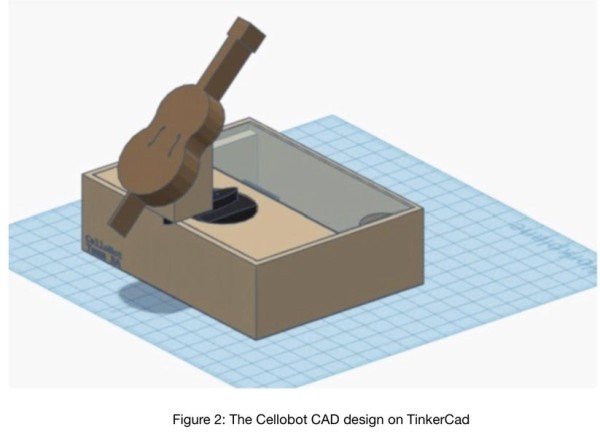
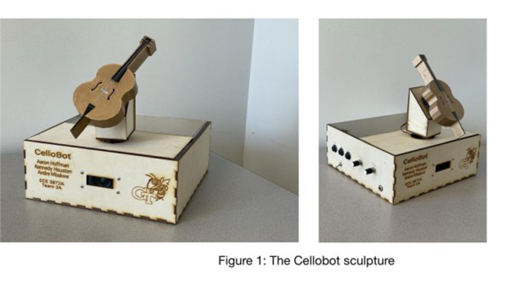
The CelloBot was designed in TinkerCad as shown in figure 2. It features a cello shape body that rotates at an angle. The on/off switch will be on the base of the sculpture, the user interface components will also be on the base of the sculpture, all the hardware will be stored inside. The purpose of the robot is to play the tune of “Row, Row, Row Your Boat” through a speaker in harmony with a conductor tune which plays preliminary notes to set tempo and octave. The CellotBot system will begin playing with other orchestra members once the play state has been activated, it will have features to adjust the tempo and change the octave of the audio being played.
Step 2: BOM (Bill of Materials)
Here is the list of all the components and parts required to build your very own CelloBot.
Materials:
• (X1) Arduino Uno Rev 3 – https://store.arduino.cc/usa/arduino-uno-rev3
• (X2) Servo motor – https://www.adafruit.com/product/2307
• Wood sheets
• Acrylic Sheets
• (X1) 9VDC 1000mA Power adapter – https://www.adafruit.com/product/63#technical-det…
• (X2) 10K Log Potentiometer – https://www.adafruit.com/product/3391
• (X2) Toggle Switch – https://www.adafruit.com/product/3221
• (X1) Mono Enclosed Speaker – https://www.adafruit.com/product/3351
• (X1) LM2596 DC-DC Buck Converter – https://www.amazon.com/LM2596-Converter-Module-Su…
• (X1) Mono Audio Amp Breakout – https://www.sparkfun.com/products/11044
• (X1) Breadboard and wires
• (X1) Wood glue
Tools:
• 3D Printer
• Laser cutter
• Soldering iron
Step 3: Software Design
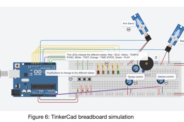
TinkerCad is also a circuit designer, where you can build and simulate before physically making a prototype. Using TinkerCad you can simulate code with a range of electronic devices.
You would want to start off by writing your C++ code for the Arduino, by writing simple functions to test out on the simulator. When working on the code for this project, I started off by testing the transition of states by using pushbuttons and LEDs and gradually added more functions such as audio playing sound, servo motor movement, and so on.
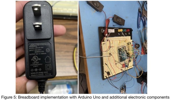
Once you have your software properly working on the TinkerCad simulator, you begin to wire it up to your breadboard, matching with your code. To test it out your breadboard you would need to get a compiled version of the program onto your Arduino Uno device:
• Download the Arduino IDE: https://www.arduino.cc/en/software,
• In your new project file write and compile your code on the IDE
• Connect your Arduino device to your computer via USB
• Go to the tools menu, click on port, then click on the device which you want to upload your code onto
• Lastly, under the sketch menu, click on upload as shown in figure 7
The code for the Arduino microcontroller can be found here: https://www.arduino.cc/en/software,
Step 4: PCB Design
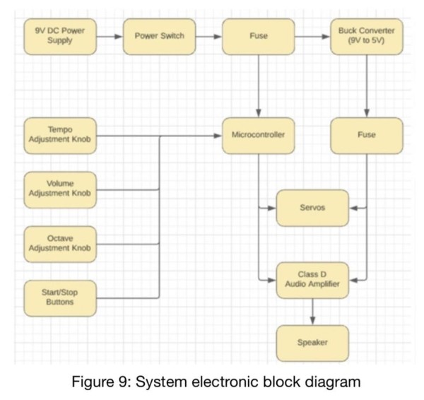
The block diagram shown above contains all the key elements of the entire CelloBot system. Using the block diagram, the PCB will be designed using the EAGLE software. Start by creating a schematic of your electronic design on EAGLE, use the schematic above as reference. Once the schematic is complete we will go ahead and begin the PCB design:
• Next in the File menu, go to switch to the board.
• In the Board Editor all your components will be clumped tangled up to the left side, on the right, there is a frame that can be adjusted. The frame is used to adjust the dimensions of your PCB.
• Place your components neatly onto the frame to be able to place the circuit board on an Arduino.
• When all components are placed appropriately, use the RATSNEST command to redraw the air wires.
• Define a ground port to the top and bottom layer of the board by drawing a polygon around the entire frame first on the top layer. Then change the name of the polygon to GND and once you hit the RATSNEST button it will fill in the ground port.
• Next click on the AUTOROUTE icon, then set the preferred direction for the TOP layer to NA. If they’re a few signals that are not traced, you’ll manually route these signals by selecting the ROUTE tool and click on an endpoint of an unrouted air wire.
• Once you are done designing your PCB you would do a design check, to make sure it is manufacturable. Click on DRC, then hit check to look for any errors, make any additional changes necessary.
• Save your PCB design and place an order for it.
Once your PCB has been delivered, you wanted to solder all the electronic components to it and begin testing and debugging.
*For additional details such as code implementation and electronic design, check out this document:
Source: The CelloBot (Robot Design Controlled by an Arduino Uno)