
Summary of The Brachistochrone Curve
The brachistochrone model explains and demonstrates the fastest path between two points under gravity, showing the cycloid solution via Snell’s law analogy. Designed for high school STEM education, it compares a cycloid track to straight and steep curves using laser-cut acrylic paths, 3D-printed guides, and a simultaneous-release timing system with Arduino and limit switches. The project teaches physics, optics, programming, 3D modeling, and fabrication, and can be built in about a week for classroom demonstrations.
Parts used in the Brachistochrone Model:
- 1 inch Pine Wood Plank (100 cm x 10 cm)
- Neodymium Magnets x 4 (1 cm dia x 0.5 cm height)
- 3D printing filament (PLA or ABS)
- M3 Threaded Inserts x 8 (optional)
- M3 Bolts x 8 (2.5 cm long)
- Wood Screws x 3 (6 cm long)
- Wood Screws x 12 (2.5 cm long)
- Arduino Uno
- Limit Switches x 4
- Push Button
- LCD Display
- Jump wires
- 3D printed parts: Control Box x1, Guide x6, End Stop x1, Pivot Arm x1, Pivot Mount x1, Release Piece x1
- Laser-cut acrylic panels (paths/tracks)
- Marbles (balls for rolling)
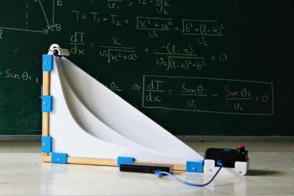
The brachistochrone curve is a classic physics problem, that derives the fastest path between two points A and B which are at different elevations. Although this problem might seem simple it offers a counter-intuitive result and thus is fascinating to watch. In this instructables one will learn about the theoretical problem, develop the solution and finally build a model that demonstrates the properties of this amazing principle of physics.
This project is designed for high school students to make as they are covering related concepts in theory classes. This hands-on project not only strengthens their grasp on the topic but also offers a synthesis of several other fields to develop. For example while building the model, students are going to learn about optics through Snell’s law, computer programming, 3d modelling, digital frabrication and basic woodworking skills. This allows an entire class to contribute dividing the work among themselves, making it a team effort. The time required to make this project is around a week and can then be demonstrated to the class or to younger students.
There is no better way to learn than through STEM, so follow on to make your very own working brachistochrone model. If you like the project do vote for it in the classroom contest.
Step 1: Theoretical Problem
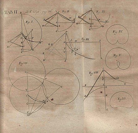
The brachistochrone problem is one that revolves around finding a curve that joins two points A and B that are at different elevations, such that B is not directly below A, so that dropping a marble under the influence of a uniform gravitational field along this path will reach B in the quickest time possible. The problem was posed by Johann Bernoulli in 1696.
When Johann Bernoulli asked the problem of the brachistochrone, on June 1696, to the readers of Acta Eruditorum, which was one of the first scientific journals of the German-speaking lands of Europe, he received answers from 5 mathematicians: Isaac Newton, Jakob Bernoulli, Gottfried Leibniz, Ehrenfried Walther von Tschirnhaus and Guillaume de l’Hôpital each having unique approaches!
Alert: the following steps contain the answer and reveal the beauty behind this fastest path. Take a moment to try and think about this problem, maybe you might crack it just like one of these five geniuses.
Step 2: Using Snell’s Law to Demonstrate
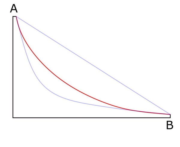
One of the approaches for solving the brachistochrone problem is to tackle the problem by drawing analogies with Snell’s Law. Snell’s Law is used to describe the path that a beam of light would follow to get from one point to another while transitioning through two different media, using Fermat’s principle, which says that a beam of light will always take the quickest route. A formal derivation of this equation can be found by visiting the following link.
Since a free-falling object under the influence of the gravitational field can be compared to a beam of light transitioning through changing media, each time that the beam of light encounters a new medium, the beam gets slightly deviated. The angle of this deviation can be calculated using Snell’s law. As one continues to add layers of reducing densities in front of the deviated beam of light, until the beam reaches the critical angle, where the beam simply gets reflected, the trajectory of the beam describes the brachistochrone curve. (the red curve in the diagram above)
The brachistochrone curve is in fact a cycloid which is the curve traced by a point on the rim of a circular wheel as the wheel rolls along a straight line without slipping. Thus if we need to draw the curve one can simply use the method above to generate it. Another unique property of the curve is that a ball released from any point of the curve will take exactly the same time to reach the bottom. The following steps describe the process of making a classroom experiment by constructing a model.
Step 3: Practical Experiment Model
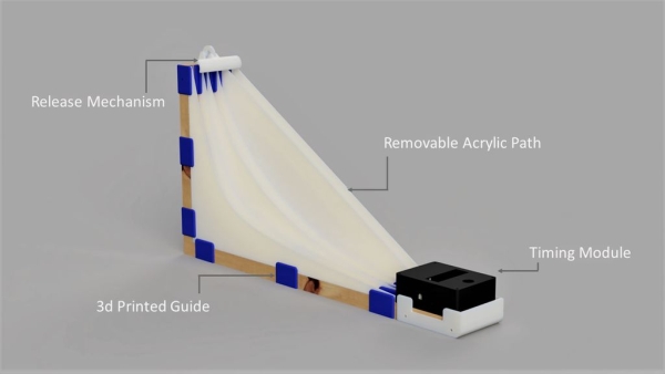
The model consists of lasercut paths that act as tracks for the marbles. To demonstrate that the brachistochrone curve is the fastest path from point A to B we decided to compare it with two other paths. As quite a few people would intuitively feel that the shortest part is the fastest we decided to put a straight slope connecting both points as the second path. The third one is a steep curve, as one would feel that the sudden drop would generate enough speed to beat the rest.
The second experiment in which the balls are released from different heights on three brachistochrone paths, results with the balls reaching at the same time. Thus our model features 3d printed guides that provide easy interchangeability between the acrylic panels letting conduct both experiments.
Finally the release mechanism ensures that the balls are dropped together and the timing module at the bottom records the timings as the balls reach the bottom. To achieve this we have embedded three limit switches that are activated when the balls trigger it.
Note: One could simply copy this design and make it out of cardboard or other materials that are easily available
Step 4: Materials Needed
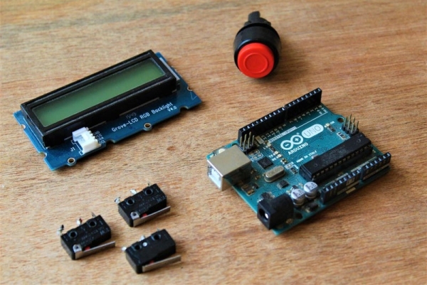
Here are the parts and supplies to make a working model of the brachistochrone experiment
HARDWARE :
- 1″ Pine Wood Plank – dimensions; 100cm by 10cm
- Neodymium Magnetx 4 – dimensions; 1cm dia and 0.5cm in height
- 3D Printing Filament– PLA or ABS are fine
- M3 Threaded Insert x 8 – (optional)
- M3 Bolt x 8 – 2.5cm long
- Wood Screw x 3 – 6cm long
- Wood Screwx 12 – 2.5cm long
ELECTRONICS :
- Arduino Uno
- Limit Switchx 4- these switches will act as the timing system
- Push Button
- LCD Display
- Jumpwire x many!
The total cost of the model came to around 30$
Step 5: 3D Printing
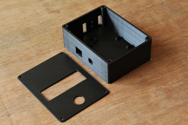
Several parts such as the release mechanism and the control box were made with the help of a 3d printer. The following list contains the total number of parts and their printing specifications. All the STL files are provided in a folder attached above, allowing one to make their needed modifications if necessary.
- Control Box x 1, 20% infill
- Guide x 6, 30% infill
- End Stop x 1, 20% infill
- Pivot Arm x 1, 20% infill
- Pivot Mount x 1, 30% infill
- Release Piece x 1, 20% infill
The parts were printed in PLA as there is no particular stress acting on the pieces. In total it took around 40 hours of printing.
Read more: The Brachistochrone Curve
- What is the purpose of the project?
To demonstrate the brachistochrone (fastest) path between two points and compare it with other paths using a classroom model. - What curve is the brachistochrone?
The brachistochrone curve is a cycloid traced by a point on the rim of a rolling circle. - How does the project illustrate the brachistochrone using optics?
It uses an analogy with Snell’s law and Fermat’s principle, treating changing gravitational potential like changing optical media to derive the curve. - What materials are required for the hardware?
Pine wood plank, neodymium magnets, 3D printing filament, M3 bolts and inserts, and wood screws as listed in the parts section. - What electronics are used for timing?
An Arduino Uno, four limit switches, a push button, an LCD display, and jump wires form the timing and control system. - Which parts are 3D printed and how many?
Control Box x1, Guide x6, End Stop x1, Pivot Arm x1, Pivot Mount x1, Release Piece x1 are 3D printed with specified infill. - Can the design be made from simpler materials?
Yes, the note states one could copy the design using cardboard or other easily available materials. - How long does 3D printing take for the parts?
The printed parts took around 40 hours in total. - How long does the overall project take to make?
The project requires about a week to build for classroom use. - What experiments does the model support?
It compares three paths (brachistochrone, straight slope, steep curve) for descent time and demonstrates equal-time descent from different heights on cycloid paths.
