Summary of Temperature Detecting Heating Control System with Arduino Mega2560
This article guides hobbyists on building a Temperature Detecting Heating Control System using an Arduino Mega2560. The system operates at 5V, utilizing a DS18B20 sensor to monitor temperature and control a heater via a relay module. It features an LCD1602 for display, a 4-bit digital tube, a buzzer for alarms, and a keyboard for input. When the actual temperature drops below the set point, the heater activates; otherwise, it stops and triggers an alarm.
Parts used in the Temperature Detecting Heating Control System:
- Arduino Mega2560 development board
- DS18B20 temperature detection chip
- LCD1602 display
- 4-bit Digital Tube
- Buzzer
- Relay Module
- Keyboard
- Red bread wire
- Black bread wire
- DuPont thread
- Bread board
Web site:
http://www.icstation.com/product_info.php?products_id=3517
Project Summary:
To help electronic DIY hobbyists, will show you how to use Temperature Detecting Heating Control System with Arduino Mega2560.
Full Project:
The temperature detecting heating control system works with DC5V voltage. This system uses DS18B20 temperature detection chip as the external detection equipment.
It works according to the external temperature collected by DS18B20. The system can make the heater work according to the temperature which has been setted. When the actual temperature is lower than the setting temperature, the heater begins to heat to make the temperature go up. When the heating temperature is not lower than the setting temperature, the heater stops working, the buzzer will alarm.
Step 1: Schematic Diagram
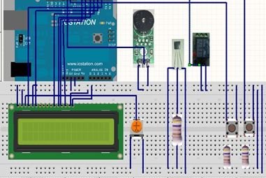
Step 2: Power Supply Line & GND Line
Plug +5V power supply and GND to the bread board from the ICSTATION MEGA development board, and the red bread wire is used as supply line, the black one as GND line.
Step 3: LCD1602
Plug LCD 1602 into the bread board, and use the DuPont thread to draw forth the digital tube pins.
Step 4: Digital Tube & MEGA2560
According to the schematic diagram, connect the pins of 4bit Digital Tube with the pins of ICSTATION MEGA development board.
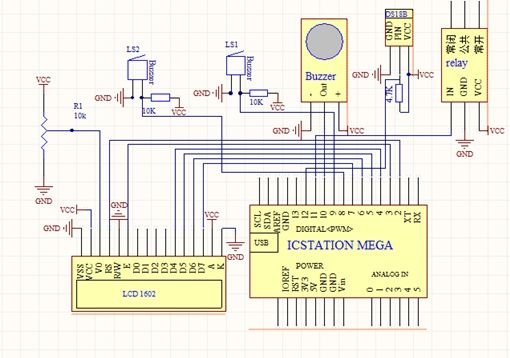
Step 5: Place the Buzzer
The two sides connect with GND and +5V
The middle board development board connects to the pin 12.
Step 6: Connection of DS18B20 & Keyboad
Step 7: Connection of the Relay Module
The relay VCC and GND respectively connect to the bread board “+” “-”, and connect to the development board pin 13.
For more detail: Temperature Detecting Heating Control System with Arduino Mega2560
- What voltage does the system work with?
The system works with DC5V voltage. - How is the temperature detected?
The system uses the DS18B20 temperature detection chip as external detection equipment. - When does the heater begin to heat?
The heater begins to heat when the actual temperature is lower than the setting temperature. - What happens when the heating temperature is not lower than the setting temperature?
The heater stops working and the buzzer will alarm. - Which pin connects to the buzzer middle board?
The middle board development board connects to pin 12. - Where do the relay VCC and GND connect?
The relay VCC and GND respectively connect to the bread board plus and minus terminals. - To which pin does the relay module connect on the development board?
The relay module connects to development board pin 13. - What color wire is used as the supply line?
The red bread wire is used as the supply line.