Summary of Temperature Controlled Fan using Arduino
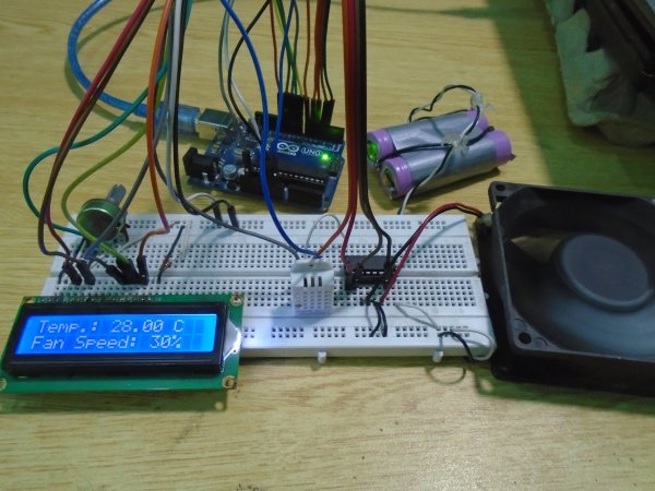
This project creates a temperature-controlled DC fan using an Arduino Uno. A DHT22 sensor monitors room temperature, and the system adjusts the fan speed via PWM to maintain comfort. An L293D motor driver IC controls the DC motor's operation, while a 16×2 LCD displays real-time data. The circuit integrates a 9V battery for power, a potentiometer for contrast adjustment, and a resistor for signal stability on a breadboard.
Parts used in the Temperature Controlled DC Fan:
- Arduino Uno
- L293D Motor Driver IC
- DHT22 Sensor
- 16×2 LCD Display
- DC Fan/motor
- 9V Battery
- 10KΩ Potentiometer
- 220Ω Resistor
- Breadboard
Here we are going to make a temperature controlled DC fan. DHT22 sensor is used to sense the room temperature and then we adjust speed of a DC fan/motor accordingly using PWM (Pulse Width Modulation). Arduino Uno is the heart of this project and a L293D driver IC is used to drive the DC fan/motor.
Components Required
- Arduino Uno
- L293D Motor Driver IC
- DHT22 Sensor
- 16×2 LCD Display
- DC Fan/motor
- 9V Battery
- 10KΩ Potentiometer
- 220Ω Resistor
- Breadboard
Circuit Diagram
Explanation
First we can connect L293D motor driver IC to Arduino as below. You can read articles L293D Motor Driver IC and H-Bridge Motor Driving for more information about the working of L293D.
- Connect pin 1 (Enable 1) of L293D to pin 5 of Arduino.
- Connect pin 2 (Input 1) of L293D to the pin 4 of Arduino.
- Connect pin 3 (Output 1) of L293D to one terminal of the DC motor.
- Pins 4 and 5 of the L293D are ground pins, connect these to common ground (battery ground + arduino ground).
- Connect pin 6 (Output 2) of L293D to the remaining terminal of the DC motor.
- Connect pin 7 (Input 2) of L293D to the pin 3 of Arduino.
- Pin 8 is Vcc2, which is the driver/motor power input, connect it to positive of the battery.
- Pin 16 is Vcc1, which is logic voltage input (voltage level of control signals provided by Arduino). Connect it to 5V output of Arduino.
After that connect DHT22 sensor to the Arduino, it is using a single wire bus for communication.
- First pin is VCC power input, connect it to 5V output of Arduino.
- Second pin is DATA output, connect it to pin 6 of Arduino.
- Third pin is NOT USED.
- Fourth pin is Ground, connect it to ground.
Now we can connect 16×2 LCD to the Arduino.
- Pin 1 is VSS, connect it to ground.
- Pin 2 is VDD, connect it to 5V output of Arduino.
- Pin 3 is VEE, for adjusting display contrast. Connect it to the variable terminal of a potentiometer whose fixed terminals are connected to ground and 5V.
- Pin 4 is RS (Register Select), it is used to select data or command register. Connect it to pin 12 of Arduino.
- Pin 5 is R/W (Read/Write). Connect it to ground since we are only writing data to LCD in this project.
- Pin 6 is EN (Enable), it is used to indicate a valid data/command in data lines (D0 ~ D7). Connect it to pin 11 of Arduino.
- Pin 7 ~ 10 are data pins (D0 ~ D3), used to transmit data/command to LCD controller. But these pins are not used in 4 bit LCD interfacing, so connect it to ground.
- Pin 11 ~ 14 are data pins (D4 ~ D7), used to transmit data/commands to LCD controller. Connect it to Arduino pins 10, 9, 8 and 7 respectively.
Read More: Temperature Controlled Fan using Arduino
- How is the fan speed adjusted?
The speed of the DC fan is adjusted accordingly using PWM based on the temperature sensed by the DHT22. - Which component drives the DC fan?
An L293D driver IC is used to drive the DC fan or motor. - What is the role of the DHT22 sensor?
The DHT22 sensor is used to sense the room temperature. - How is the LCD contrast controlled?
The contrast is adjusted by connecting pin 3 (VEE) to the variable terminal of a potentiometer. - Can I read more about this project online?
Yes, you can read more at Temperature Controlled Fan using Arduino. - What is the function of the 220Ω resistor?
The article lists a 220Ω resistor as a required component for the project, though specific wiring details are not elaborated beyond its inclusion in the parts list. - Does the DHT22 use multiple wires for communication?
No, the DHT22 uses a single wire bus for communication. - Where is the logic voltage input connected on the L293D?
Pin 16 (Vcc1) is the logic voltage input and connects to the 5V output of the Arduino.