What’s better in the morning than a hot cup of tea?
You should keep to the brewing time so that the tea tastes the way you want it to. Unfortunately, there’s always a lot to do and the timer beeps when you’re somewhere else. So we need an automatic “tea extraction machine”…..
As always, there are already a few things on the net. But they didn’t really fulfill all my wishes.
Here are the requirements:
- The height of the arm should be easily adjustable for different sized cups and pots.
- Also suitable for heavy tea filters
- The brewing time should be flexibly adjustable – the remaining brewing time should be displayed
Later (after trials with the customer (my wife)) a few more wishes were added.
- Interruption of the brewing process
- Adjustability of the brewing time during the brewing process
- Sound for welcoming and when the tea is ready
What are the main differences to other approaches?
- Teatimer2.0 is robust and easy to use for a daily use.
- You can control all functions with one hand, while the other is free for fill in the water etc.
- You can use it for nearly any size of pots & cups.
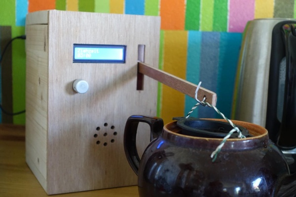
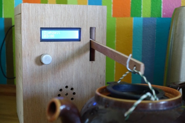
Step 1: Teatimer 2.0 in Use
To show how Teatimer2.0 works – here is a small video.
- Connect Arduino to power – it will display the welcome screen and sound the MP3 greeting.
- Press or turn the rotary encoder once.
- The height adjustment of the arm will be displayed.
- Insert the tea strainer or tea bag and fill in tea
- Move the arm to the desired brewing position.
- Press the rotary encoder.
- The time setting is displayed.
- Set the time and brew the tea.
- Press the rotary encoder.
- The time counts down.
- During the brewing process, the time can be adjusted and thus the brewing process can be aborted.
- When it reaches zero, the arm slowly rises and the message “tea is ready” (or whatever you have recorded) occurs.
- After pressing the encoder, the greeting is displayed again.
- After 15 minutes (can be adjusted in the sketch under #define INTERVALL_SHUTDOWN) the Arduino goes into a “half” standby – the display goes dark and the servo is turned off. This reduces the power consumption considerably – a real shutdown was too much work for me here …
- If you press the encoder for two seconds the standby is initiated immediately.
Step 2: What Previous Experience Do I Need?
Previous experience with Arduino is useful but not necessary.
- You should have some experience with electronics to assemble and test the system.
- You should be able to solder and use a multimeter.
- And then of course creativity and tinkering experience.
- Especially the topic of housing and mechanical integration took me some time and trial and error until everything was the way I wanted it.
Step 3: Material
- Arduino Leonardo (UNO works too – but then you have to use software serial)
- USB power supply with Micro-USB connector
- LCD Display 1602 IC2
- Rotary Encoder KY-040
- Servo motor MG995 180° (or 270° – NOT 360°)
- Small breadboard
- Jumper wires
- Wooden boards for the case e.g.
- 2 x 15mm x 150mm x 150mm (solid wood, multiplex, plywood, …)
- 2 x 15mm x 150mm x 200mm (solid wood, multiplex, plywood, …)
- 2 x 5mm x 150mm x 230mm (= 200mm + 2 x thickness of boards – here 2 x 15mm) (plywood) –
- Wooden strip for the arm e.g.
- 5mm x 15mm x 230mm (plywood)
- Wooden blocks for mounting the servo e.g.
- 4 x 15mm x 20mm x 20mm (solid wood, multiplex, plywood, …)
- PVC hard foam 2mm (alternatively cardboard, plywood, …)
- 35mm x 100mm – mountingplate for servo
- 30mm x 80mm – frame LCD
- Screws
- 12 x 4,5mm x 30mm (housing)
- 2 x 3mm x 15mm (mounting plate of the servo)
- wire / cord
- optional
- MP3 module DFPlayer mini
- resistor 1kOhm
- Loudspeaker (e.g. 8 Ohm / 2 Watt)
- micro SD card
Step 4: Tools
You should get along by with a small workshop equipment. Depending on
how you implement in particular the subject of housing and mounting the sensors it can be different.
- Drill
- Saw
- File
- Sandpaper
- Hot glue gun
- Optional – Soldering iron
Step 5: Wiring Table
KY-040 <-> Arduino
- CLK <-> 11
- DT <-> 10
- SW <-> 3
- + <-> 5V
- GND <-> GND
LCD <-> Arduino
- GND <-> GND
- VCC <-> 5V
- SDA <-> SDA
- SCL <-> SCL
Servo <-> Arduino
- GND (brown cable) <-> GND
- + (red cable) <-> 5V
- Control (orange cable) <-> 8
DFP MP3 module <-> Arduino Leonardo (different for UNO)
- RX <-> TX – Attention! Use resistor 1kOhm
- TX <-> RX
- VCC <-> 5V
- GND <-> GND
- SPK1 <-> Speaker
- SPK2 <-> Speaker
Step 6: MP3 Sound
If you want, you can be greeted at the beginning and let you know when the tea is ready.
But you don’t have to do this to use the TeaNik’s function. You can then simply leave out the MP3 player and the speaker and don’t have to change anything.
- Format Micro SD card (FAT32)
- Record soundfiles (greeting & message that the tea is ready) e.g. with a cell phone.
- If necessary convert soundfiles to .wav or .mp3 (SW on the internet)
- Save soundfiles
- Save greeting under 0001.mp3 and message under 0002.mp3
- Insert micro SD card into DFP MP3 module
- Start system
- Adjust volume if necessary – under #define MP3_VOLUME
Step 7: Assembly & Startup
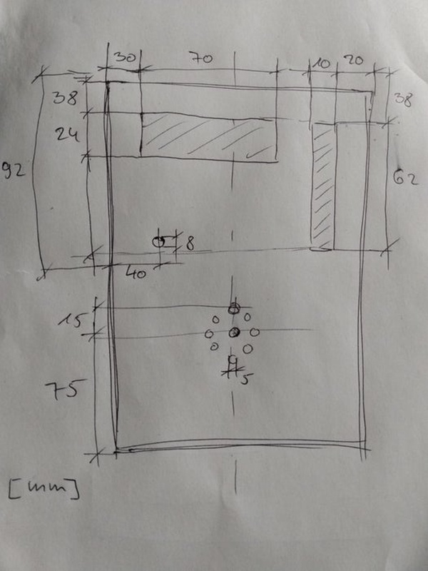
Housing 1/2
- Saw hole in front panel for LCD
- Saw hole in front panel for arm
- Drill hole in front panel for encoder
- Drill holes in front panel for loudspeaker
- Pre-drill first side panel and screw to bottom panel (4.5mm x 30mm screws) – Fix front side with hot glue
LCD display
- Cut out frame from PVC hard foam
- Fix LCD display on frame with hot glue
- Fix frame on front panel with hot glue
Arm
- Drill holes in the wooden strip – once for a hook and once for the mounting screw on the servo
- Glue arm of servo to arm with hot glue – pay attention to the fixing hole
Servo on plate
- Screw servo to wooden block
- Cut out mounting plate from hard PVC
- Fix the blocks to the plate with hot glue
- Glue the blocks in the box under and over the display
Install electronics
- Cut out PVC hard foam plate for Arduino, glue Arduino with little hot glue, glue plate in bottom part so that Arduino is flush with rear edge
- Measure the position of the USB port and drill a hole in the back panel at this position.
- Glue breadboard to bottom part
- Glue loudspeaker to front panel
- Plug DFP MP3 module into breadboard (Attention: the breadboard has tracks in one direction – each connection must have its own track)
- Connection diagram of DFP MP3 module – from above – pay attention to the indentation
- See details here –> https://wiki.dfrobot.com/DFPlayer_Mini_SKU_DFR0299
- Connect 1kOhm resistor to RX of DFP MP3 module so that the second pole is on the other side of the breadboard
- Connect all electronics one after the other as described in the wiring table
- Attention – with LCD displays a common mistake is that the contrast is not set correctly, adjust it by potentiometer on the backside after everything is wired.
- Connect the servo – but do not install it yet
Power supply
- Apparently the built-in voltage regulator is not very powerful.
- When using a 9V power supply, the display kept failing.
- I recommend to use a USB power supply.
Upload the Sketch
If you have no previous experience with
Arduino, it is best to look at a few websites on the net. Even if you don’t have to program anything here, it is helpful. Here are the main steps.
- Install the Arduino IDE Connect Arduino via USB cable
- Put the Sketch in a folder with the same name and open it in Arduino IDE Select under Tools / Board / Arduino AVR / Arduino Leonardo
- Under Tools / Port select the port to which the Arduino is connected
- Download the sketch from https://github.com/surfer-max/Teatimer2
- Under Sketch / Upload upload the sketch
Adjusting & installing the servo
- A servo always moves to the center position as soon as it is connected to voltage.
- Therefore, before installation, connect the servo once, connect the Arduino briefly to voltage so that the servo moves to the center position.
- In this position, attach the arm so that it points to the desired start position (this can be adjusted later with the knob).
- Screw the plate with the servo onto the blocks (with 3mm x 15mm screws).
- It is still important to set the max / min positions of the servo correctly.
- If they do not fit, the servo may hit the limits in the box and it or the bracket may be damaged.
- Therefore set the max / min values to the center position first if necessary.
- #define MIN_HEIGHT 60 // maximum height of the arm
- #define MAX_HEIGHT 60 // minimum height of the arm
- Insert the servo with the arm into the housing and screw it tight.
- Then adjust the position by turning the encoder to the end positions and note the values.
- Adjust values max / min
- #define MIN_HEIGHT 85 // maximum height of the arm
- #define MAX_HEIGHT 20 // minimum height of the arm
- #define START_HEIGHT 20 // start height of the arm
- usefull if set to the maximum height
Housing 2/2
- Pre-drill second side part and screw to top part and bottom part (4,5mm x 30mm screws)
- Pre-drill back side and screw together with side parts (4,5mm x 30mm screws)
Step 8: Conclusion & Acknowledgements
Teatimer2.0 is in daily use and has proven itself well.
Thanks to
- the many ideas and instructions on the Internet.
- my wife for the good customer feedback and optimization suggestions.
- my son for the good tinkering and developing.
- my daughter for the voice output.
- deepl for the translation.
Source: Teamaker 2.0