System for detecting objects using Arduino

Project Abstract

I’ve been exploring the idea of creating a robot using Arduino technology for a while now. This project marks the initial phase of this ongoing hobby endeavor. The aim is to construct an object detection system that can be integrated into a semi-autonomous robot in the future.

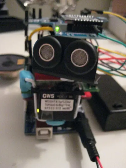
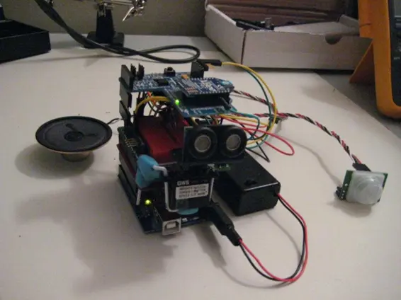
The system employs an ultrasonic range finder to identify obstacles in close proximity to the device. To provide a sweeping view, the ultrasonic sensor is affixed to a sub micro servo. Additionally, a Passive Infrared (PIR) sensor is utilized to activate the SONAR when motion is detected.

Sensor readings and distance measurements are transmitted wirelessly via 802.15.4 to a computer for visual representation. Furthermore, the microcontroller’s code triggers audible alerts using a serial-driven voice synthesizer chip connected to a small speaker.

Status

The project has reached its successful completion, achieving my objective of seamlessly integrating all underlying technologies. The device can effectively capture SONAR readings at designated servo angles and wirelessly transmit them to a Processing sketch, where they are presented for straightforward analysis. Furthermore, the device is equipped to vocalize and announce essential status updates and object detection occurrences.

In the subsequent sections, I will elaborate on several aspects that could benefit from further enhancement. Among these are XBee wireless programming and the exploration of a sturdier power supply solution.

Specification

Hardware

I constructed this device using the Arduino Duemilanove microcontroller, primarily because I already owned one and had prior experience interfacing with it, aiming to deepen my understanding. Arduino, an open microcontroller platform, employs an AVR-C derivative known as Wiring. Its compatibility with shields for prototyping, SpeakJet, and XBee made it a suitable choice for this project.

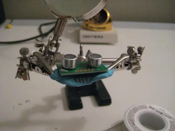
For the SONAR component, I opted for a Devantech SRF10 ultrasonic sensor mounted on a Grand Wing Servo (GWS) sub micro servo. Mounting the SRF10 involved using two screws and the SRF10 mounting kit. Since each servo shipped with only one screw of the correct size for mounting the servo horn, ordering two servos proved beneficial. Aligning the circular horn with the mounting kit required some patience due to the small size of the parts and screws.

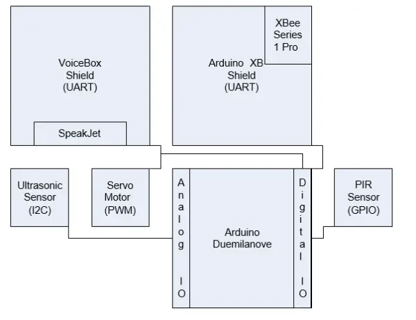
The SRF10 utilizes an I2C interface, utilizing analog pins 4 and 5 in alternate function I2C mode for communication. Connecting it this way enables the Wire library to communicate with the sensor via the Arduino’s I2C bus.

Digital output capabilities of the Arduino are employed for controlling the servo to which the ultrasonic sensor is attached. The Servo library effectively abstracts Pulse Width Modulation (PWM), which governs the servo’s movement.

A digital input is utilized for detecting motion within range using a Parallax Passive Infrared Sensor (PIR). This straightforward device sets the pin high upon sensing motion.

To enable speech functionality, my Arduino code communicates with a Magnevation SpeakJet via a software serial connection. I opted for the NewSoftwareSerial library instead of the built-in SoftwareSerial library due to its efficiency and higher speed capabilities.

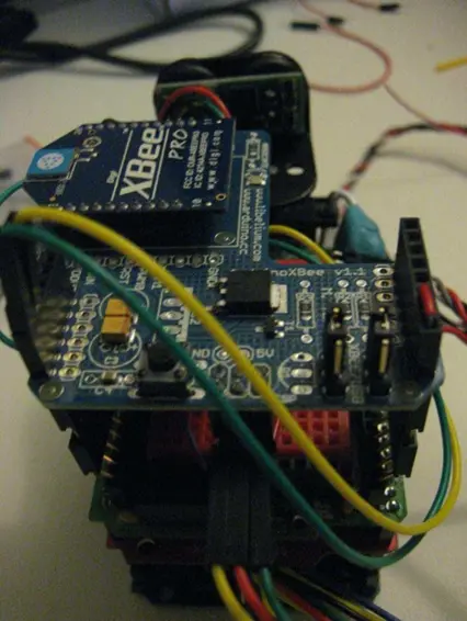
For interfacing with the computer, the XBee serves as a serial port replacement for transmitting sensor data from the microcontroller. Two Digi XBee Series 1 Pro chips were employed for this task.

Wiring Code

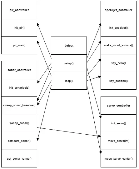
To ensure seamless integration of all hardware components, I developed four libraries. The Wiring code for each library is provided in the attachment accompanying this paper. To enhance reusability, each library includes #define statements for configuring different elements. Below are the names of the libraries along with their respective configuration elements:

The pir_controller initializes the Passive Infrared Sensor (PIR) and waits for a motion detection event:

  • #define PIR_PIN specifies the digital pin number assigned to the PIR.
  • #define PIR_CALIBRATION_TIME determines the duration for PIR calibration.

The servo_controller initializes the servo and controls its movement.

  • #define SERVO_PIN specifies the digital pin number assigned to the servo.
  • #define MIN_DEGREE defines the minimum degree to which the servo can be moved.
  • #define MAX_DEGREE defines the maximum degree to which the servo can be moved.
  • #define DEGREE_STEP defines the increment by which the servo moves during panning.
  • #define MID_DEGREE specifies the midpoint degree position of the servo during a sweep.
  • #define SWEEP_RESOLUTION determines the total number of steps in a full sweep.

The sonar_controller initializes the SRF10, retrieves range values, and manages sweep rotation by calling the servo_controller.

#define SRF_ADDRESS stores the address of the SRF10.

The speakjet_controller initializes the SpeakJet and articulates various pre-stored messages stored within the library.

Processing Code

I created a straightforward processing sketch that plots the Cartesian coordinates of the sensor data and links these points with lines. The code was quickly assembled by combining an example I stumbled upon (http://www.uchobby.com/index.php/2009/03/08/visualizing-sensor-with-arduino-and-processing) with snippets of J2ME code borrowed from a LIDAR plotting routine I developed last semester. You can find the processing code in the attachment accompanying this document.
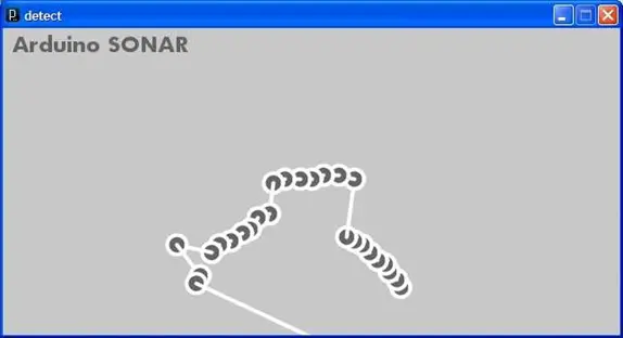
Processing Sketch for Visualization
Figure 1: Processing Sketch for Visualization
Supply List Price SKU: Supplier
Ardino IDE $0.00 N/A http://www.arduino.cc
Processing IDE $0.00 N/A http://processing.org
X-CTU Configuration Software $0.00 N/A http://www.digi.com
Libelium Xbee Shield $24.95 SKU#

51835

www.hvwtech.com
Devantech SRF10 Tiny Ultrasonic

Ranger

$59.95 SKU#

40326

www.hvwtech.com
Devantech SRF10 Mounting Kit $8.95 SKU#

40360

www.hvwtech.com
Sub Micro Servo – NARO HP BB $15.95 SKU#

22150

www.hvwtech.com
XBee Series 1 Pro (x2) $75.90 WRL-

08690

www.sparkfun.com
XBee Exporer USB $24.95 WRL-

08687

www.sparkfun.com
9V Switched Battery Case with Barrel

Jack

$5.00 N/A www.sparkfun.com
VoiceBox Shield $39.95 DEV-

09624

www.sparkfun.com
Arduino Duemilanove $29.99 DEV-

00666

www.sparkfun.com
ProtoShield Kit $16.95 DEV-

07914

www.sparkfun.com
Mini Breadboard $3.95 PRT-

08800

www.sparkfun.com
Jumper Wire Kit $6.95 PRT-

00124

www.sparkfun.com
Jumper Wires Premium 6″ M/F Pack

of 100

$24.95 PRT-

09139

www.sparkfun.com
Break Away Headers – Straight $2.50 PRT-

00116

www.sparkfun.com
Break Away Headers – Right Angle $1.95 PRT-

00553

www.sparkfun.com
Arduino Stackable Header – 8 Pin (x2) $1.00 PRT-

09279

www.sparkfun.com
Arduino Stackable Header – 6 Pin (x2) $1.00 PRT-

09280

www.sparkfun.com
Loktite Mounting Putty $1.88 N/A Wal-Mart
Parallax PIR Sensor Module $9.99 276-033 Radio Shack
Nylon Wire Ties $2.49 278-1632 Radio Shack
Coat Hanger $0.00 N/A N/A
Assorted Wire Bundles $0.00 N/A Junk computer
Small Speaker $0.00 N/A Junk computer

Table 1: Parts List

Implementation & Construction

Ultrasonic Sensor Assembly

1. Delicately attach header pins to the SRF10, optionally using mounting putty to secure them in place.

attach header pins to the SRF10

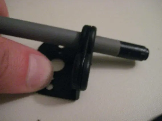
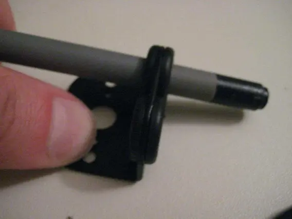
2. Insert the rubber grommets into the SRF10 mounting bracket, using a pen if necessary to compress them into a precise circular form.

Insert the rubber grommets into the SRF10 mounting bracket

3. Carefully slide the SRF10 into the rubber grommets.

Attach the SRF10 mounting kit

Secure the SRF10 mounting kit to the servo horn using small screws.

Connect four prototyping cables to the sensor. To prevent them from slipping off during servo panning, secure them with a wire tie.

Avoid screwing the servo horn into the servo for now. The horn fits snugly enough onto the servo without screws, allowing for easy adjustments to the sensor alignment within the roughly 130-degree rotation range of the Pico servo.

Shield Assembly

Arduino shields typically require some degree of assembly. Even pre-built shields often need header pins to be soldered on. Refer to the assembly documentation as necessary.

  1. Assemble the ProtoShield by following the instructions available at: http://www.ladyada.net/make/pshield/solder.html.
  2. Use double-sided tape to attach the mini breadboard to the ProtoShield.
  3. Solder female header pins and speaker connection pins to the VoiceBox shield, which contains the SpeakJet and amplification circuitry. To save space, I used right-angle connectors. Mounting putty is very helpful for holding the components in place while soldering.
  4. If desired, place a small jumper between digital pins 0 and 2 to command the SpeakJet using the PheaseALator software.

NOTE: Ensure the female headers are aligned correctly, as misalignment can make stacking the shields difficult.

Arduino Assembly

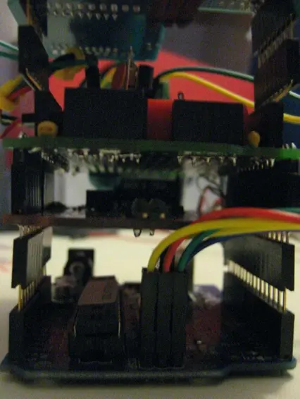
At this stage, we are ready to stack the shields and start building the prototype.

  1. Begin by placing the Arduino on a flat surface.
  2. Attach jumper wires to all the ICSP header pins. These will be connected to the XBee shield later. Use zip ties to keep them organized.
  3. Insert stackable header pins into the 6 and 8 pin rows. This step is necessary to provide clearance for the jumper wires added earlier.
  4. Stack the VoiceBox shield on top of the Arduino.
  5. Stack the ProtoShield on top of the VoiceBox shield.
  6. Depending on your ProtoShield model, you might find that the pins on top do not align correctly for stacking an additional shield. You can fix this by connecting two stackable headers and carefully bending the pins on one of them to correct the offset.

stack can be completed by placing the XBee shield

7. Complete the stack by placing the XBee shield onto the topmost layer of stackable header pins and connecting the wires to the ICSP header on the XBee shield. Using right-angle connectors facilitates quick removal of these connections for USB programming.

Servo Mount

This section allows for creative interpretation, but the following steps outline the design I improvised for this prototype:

  1. Insert the rubber grommets included with the servo into their designated mounting slots.
  2. Cut a piece of coat hanger to a length of approximately one foot.
  3. Using pliers, bend the hanger wire so it fits into the mounting grommets and holds the servo. I discovered that angling it slightly upward helps prevent the SONAR sensor from detecting the ground instead of outward.
  4. The ProtoShield and VoiceBox shield have pre-drilled holes for PCB offset pads. Utilize these holes, along with mounting putty or hot glue, to securely attach the servo. Ensuring a stable servo mount is crucial for maintaining accuracy.

a loose servo mount will sacrifice a lot of accuracy

Breadboard Detail

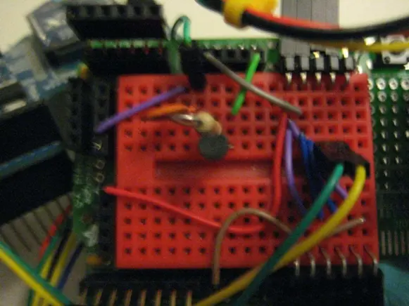
This step is optional, but it results in a neater assembly with fewer stray wires that could obstruct the servo’s rotation.

a cleaner package with less stray wires to interfere with the servo rotation

  1. Use 90-degree header pins to add connectors for the PIR, servo, and I2C connections.
  2. Route the appropriate power, ground, and GPIO pins to each connector using flat jumper wires.
  3. Double-check all connections.
  4. Verify everything once more and then connect the wires to the header pins. If you have any old computers, you might be able to salvage some lengths of multi-strand wires with pre-attached headers.

the XBee wireless programming circuit

5. At this stage, you might want to try breadboarding the XBee wireless programming circuit detailed at: http://www.ladyada.net/make/xbee/arduino.html. Although I didn’t have much success with the XBee shield, it seems feasible, and I plan to revisit this later.

XBee Configuration

XBee Configuration

The provided link offers a comprehensive tutorial on configuring XBee adapters to communicate with each other. Here are some tips:

  1. Connect the XBee Explorer USB to your PC and install FTDI drivers if necessary. Always ensure that you insert the XBee in the correct orientation to avoid damaging it.
  2. Utilize the X-CTU tool downloaded from the Digi support site to make the documented changes. I’ve found it helpful to adjust parameters, firmware, and baud rates separately, as the XBee chip can be sensitive otherwise.
  3. If you encounter difficulties connecting the tool to the XBee, remain calm. It’s unlikely that you’ve caused any permanent damage through misconfiguration. Verify that the baud rates in X-CTU match those programmed into the XBee. You might have success by enabling API mode and reflashing the firmware. Another method is to short the ground and RST pins to force the XBee to restart. Remember, online resources can be helpful in troubleshooting.
  4. The Funnel IO project has released an XBee configuration that functions effectively, provided your XBee chips are running the supported firmware version: http://funnel.cc/Hardware/FIO
  5. For wireless programming, it’s preferable to use an XBee Series 1 chip. Series 2 (now 2.5) chips do not support transparent IO line passing, necessary for resetting the Arduino. Alternatively, you can perform the reset in software, but it’s not optimal, as timing it correctly can be challenging.

Functional Testing

Power Issue

After assembling everything, I disconnected the ICSP pins from the XBee shield and proceeded to develop code using USB. However, I observed that the speaker would output gibberish when the servo moved, and the ultrasonic sensor would occasionally crash while attempting to obtain readings. This issue stemmed from the inconsistent power supply provided by the USB connector.

I attempted to address this by using capacitors, but ultimately, the only effective solution I found was to utilize a separate AC transformer during testing. I discovered that a 9V battery is unsuitable for this application. It struggles to supply sufficient current, particularly as its charge diminishes rapidly over time. I intend to conduct further research on battery options and invest in a more robust rechargeable battery kit.

Ultrasonic Sensor Accuracy Issue

Initially, I encountered numerous challenges in obtaining consistent readings from the sensor. To address this, I devised functional tests involving multiple sonar sweeps and calculated the absolute value deltas between them. I recorded these sensor readings and delta calculations in a spreadsheet. Additionally, I conducted a test scenario where I took multiple sensor ranging samples at each step. It was during this process that I observed larger deltas between the first and second ranges compared to those between the second and third readings. Moreover, larger deltas were evident at both ends of the sweep.

The data clearly indicated that insufficient time was allocated for the servo to move. By increasing the delay between readings to allow the servo more time to adjust its position, and by introducing delays at the beginning and end of the sweep, I achieved significantly more reliable results. Furthermore, I observed that reducing the analog gain sensitivity during these tests appeared to mitigate anomalous readings between passes.

SpeakJet Command Issue

This chip exhibited unpredictable behavior, seemingly speaking at random intervals without adherence to commands. It appeared to prioritize event pins over continuous serial commands in its design. I attempted to address this issue by switching to the NewSoftSerial library and breaking sentences into smaller segments, incorporating delays into the routine that transmitted each segment. However, these measures proved ineffective in resolving the issue.

The ultimate resolution, not found in any documentation I came across, involved adding a SpeakJet command to insert a 0 ms pause at the conclusion of every character array before transmitting it to the SpeakJet. This acted as a string terminator, preventing previous commands from randomly overlapping with subsequent ones. It proved to be a straightforward remedy for a vexing issue that took days to unravel.

Setup microcontroller and IDE Completed
Configure XBee interface Completed
Research sensor options Completed
Research servo options Completed
Order parts as needed Completed
Build basic test apparatus Completed
Interface with servo Completed
Test servo range of motion Completed
Interface with I2C sensor bus Completed
Interface with SpeakJet Completed
Interface with PIR Completed
Write pir_controller Completed
Write servo_controller Completed
Write sonar_controller Completed
Write speakjet_controller Completed
Assemble travel-friendly prototype Completed
Write Processing sketch Completed
Calibrate ultrasonic sensor output Completed
Refine sonar_controller Completed
Refine speakjet_controller Completed
Test completed code Completed

Table 2: Milestone Chart

Hardware Block Diagram
Figure 2: Hardware Block Diagram
Software Block Diagram
Figure 3: Software Block Diagram
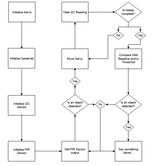
Flowchart of sensor analysis logic
Figure 4: Flowchart of sensor analysis logic

Retrospective

I’m pleased with my decision to complete this project using Arduino. It marked my first substantial coding endeavor on this platform, and compared to writing C for the Zilog ZNEO, creating Wiring libraries for Arduino proved to be a more enjoyable and efficient experience. While my time with the ZNEO provided valuable insights into low-level operations, it’s refreshing not to be bogged down by such concerns.

A key takeaway from this project is the finicky nature of sonar technology. Factors like positioning, timing, and environmental conditions can significantly influence readings. I found the performance of the SRF10 in this specific scenario disappointing due to its broad beam pattern, necessitating extensive fine-tuning to achieve accurate readings as the servo rotated.

In hindsight, I might have sought out a sensor with a narrower beam pattern. Integrating an infrared range finder would also have been beneficial, given the relatively long time required to capture ultrasonic range samples. Nonetheless, the broad beam pattern of the SRF10 may still be suitable for stationary installations or situations where the servo’s movement is sporadic, making it a valuable asset for future projects.

One area requiring further attention is the integration of XBee with Arduino. Initially, I acquired Series 2 Pro XBee chips, unaware of their limitations regarding wireless Arduino programming. Upon realizing this, I procured new Series 1 XBee chips. However, I’ve yet to achieve wireless uploading of Arduino sketches, a feature I’m keen to implement.

I believe many of my issues with programming the SpeakJet could have been mitigated by integrating a text-to-speech processor. Consequently, I intend to explore acquiring a TTS256 or similar component and integrating it into the prototype area of the VoiceBox shield.

As mentioned earlier, battery power is another area requiring consideration. A 9V battery proves inadequate for this project’s demands, highlighting the need for a more robust, long-term portable power supply solution, such as a higher-output rechargeable battery.

Attachments

  1. Arduino Code
  2. Processing Code
  3. Hardware Block Diagram
  4. Software Block Diagram
  5. Process Flowchart

Follow this link for complete project: System for detecting objects using Arduino


About The Author

Ibrar Ayyub

I am an experienced technical writer holding a Master's degree in computer science from BZU Multan, Pakistan University. With a background spanning various industries, particularly in home automation and engineering, I have honed my skills in crafting clear and concise content. Proficient in leveraging infographics and diagrams, I strive to simplify complex concepts for readers. My strength lies in thorough research and presenting information in a structured and logical format.

Follow Us:
LinkedinTwitter

Leave a Comment

Your email address will not be published. Required fields are marked *

Scroll to Top