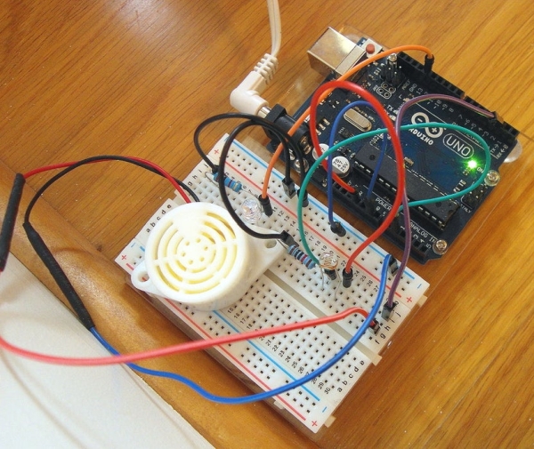
Most technology Instructables are fun to construct, and often easy to build. This is one that shares those features, but also solves a practical problem we had.
To prevent fading of furniture, carpet, and the wood flooring in our foyer, my spouse and I installed one-way blackout shades. However, after installation and use, a problem arose. The air in the foyer began to have a slightly “musty” odor as no sunlight was coming in. My solution was to build a direct sunlight detector, allowing us to close the shades only when the buzzer went off. On overcast days the shades would stay open, as the direct sunlight would not set the alarm off (we live in the Eastern US, so overcast days are not uncommon). It also meant that we could leave the shades open until we heard the alarm on clear days. The result – all the “mustiness” is now gone and as a bonus the foyer is less “gloomy”. A quick, inexpensive and winning solution on all counts. The video shows the alarm “in action”.
Like many readers and posters here, I really like LEDs and so have added one to this project. However, it is optional and not a requirement.
Step 1: What’s Needed
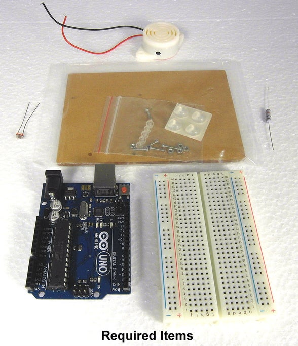
Required Items
– 95DB 3-24v High-decibel Electronic Buzzer
– An Experimental Prototype Board
– A Half-Size, 400 tie points, Breadboard
– An Arduino UNO R3
– A 10k Resistor (1/4 to 1 Watt)
– A photoresistor, almost any will do (e.g., 112582, 5516, 5528, 5537, 5539, or 5549)
Optional Items
– Two Pieces Heat Shrink Wire Wrap (Size 2.5 x 40mm)
– An LED (any color in 3mm, 5mm, or 10mm size)
– A 2k Resistor (1/4 to 1 Watt)
The optional items are just that. While I used shrink wrap to cover the solder joints to the buzzer, black electrician’s tape should work just as well. I added the LED so that in addition to the sound of the alarm it would blink on and off when direct sunlight was detected. However, since the high-decibel alarm goes off when this is the case, the LED and its 2k resistor can be left off without any lose in detection function.
Step 2: Connecting the Arduino UNO and Half-Size Breadboard to the Experimental Platform.
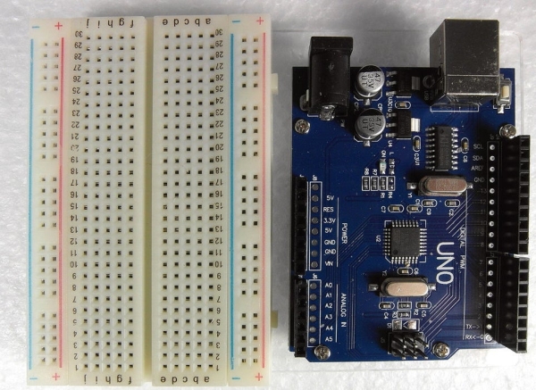
See my earlier Instructable, “Experimental Platform For the Arduino UNO R3 – How To Prepare It For Use“, at https://www.instructables.com/id/Experimental-Platform-for-the-Arduino-UNO-R3-How-t/ to see how this can be easily done.
Step 3: Alarm Wires
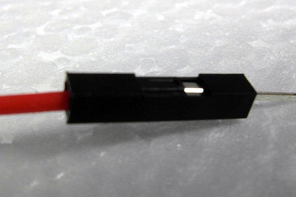
I removed the plastic cover on one side of a red Dupont male-to-male cable and soldered the pin to the red lead from the alarm. I did the same thing with a dark blue Dupont cable and soldered it to the black wire from the alarm. I covered both solder joints with heat shrink wire wrap (see 1st photograph), although as noted above black electrician’s tape will work as well. I connected the red wire to the breadboard and then, using an additional jumper cable, connected that wire to digital socket two of the Arduino Uno
That is,
– Red wire from alarm to digital socket 2 on UNO
I connected the black wire from the alarm to the ground rail on the breadboard which went to a GND pin on the UNO.
That is,
– Black wire from alarm to GND socket on UNO
Step 4: Adding the Optional LED
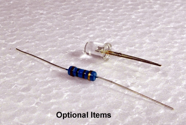
The positive side of the LED is connected to digital socket 12 of the Arduino UNO, and the negative side is connected through a 2k resistor to a UNO GND socket.
I do not like excessively bright, to me, LEDs so I used a 2k resistor here. If you do not mind, or you would like, a brighter LED you may want to use a 330-560 ohm resistor instead of the 2k one I used.
That is,
– Long wire on LED to UNO digital socket 12
– Short wire on LED, going through a 2k resistor, to UNO GND socket.
Step 5: Adding the Photoresistor
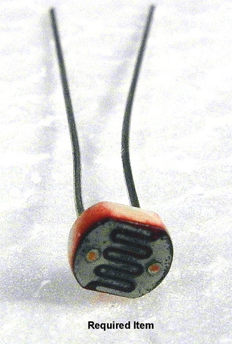
I used a T5516, but as noted above almost any photosensitive resistor will do. One side of the photoresistor goes to 5v on the Arduino. The other side goes through a 10k resistor to a GND socket on the Arduino. I connected a wire from GND on the Arduino UNO to the negative rail on the breadboard and used it for all my ground connections. The 10k resistor and photoresistor formed a voltage divider. I took the location on the breadboard where the photoresitor connected to one side of the 10k resistor and connected it to analog socket A1 to be able to obtain photoresistor measurements of the light.
That is,
– One side of the photoresistor to 5v on the UNO
– The other side of the photoresistor connects on the breadboard to a 10k resistor and then that resistor goes to ground.
– Lastly, the location where the photoresistor and 10k resistor join was connected to UNO analog socket A1.
Interesting discussions, about photoresistors can be found in the Instructables, “How to use a Photoresistor (or photocell) – Arduino Tutorial” by codebender_cc and “Photoresistors” by OlaC.
Step 6: The Sketch
Enter the sketch below into the Arduino IDE, and run it.
int photoresistorPin = A1; // Photoresistor pin connection
int ledPin = 13; // LED pin connection
int dacValue = 0; // Store the value read from the sensor
int buzzerPin = 2; // Buzzer pin connection
unsigned int x=65535; // Stores mapped dac value (ranges from 0 – 100%)
void setup() {
pinMode(ledPin, OUTPUT);
pinMode(buzzerPin, OUTPUT);
pinMode(photoresistorPin, INPUT);
}
void loop() {
dacValue = analogRead(photoresistorPin);
x = map(dacValue, 0, 1023, 0, 65000);
x = round(x/650.0); // To obtain a range from 0 to 100
Serial.println(x);
if(x >= 95) {
digitalWrite(buzzerPin, HIGH);
digitalWrite(ledPin, HIGH);
delay(250);
digitalWrite(ledPin, LOW);
delay(100);
}
if(x< 94) digitalWrite(buzzerPin, LOW);
}
Step 7: Afterwards
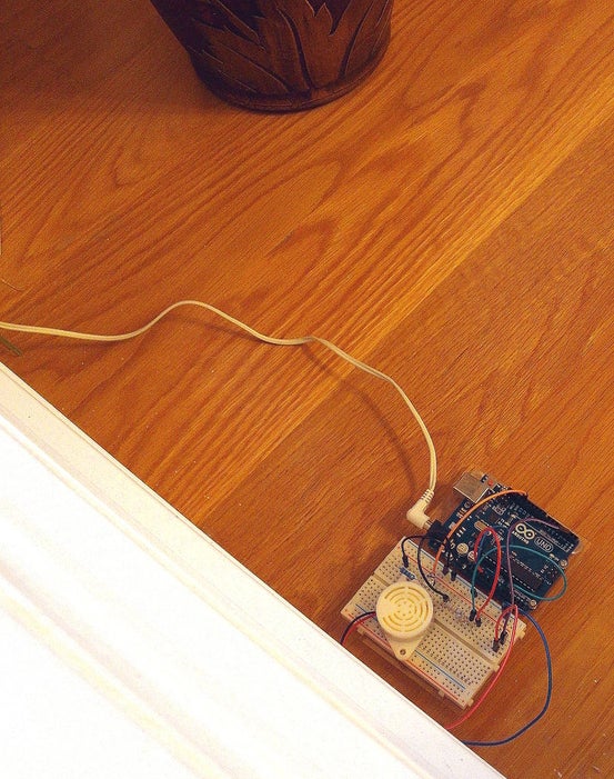
The last picture shows the assembled detection alarm systems in the foyer from somewhat of a distance. The first photograph shows an assembled system close-up. I powered my UNO using a 9v DC “wall wart”. However, power can be provided to the UNO in a variety of other ways, including battery if you need a portable sunlight detector. Depending on where you place this alarm, and the photoresistor you use, you may want to change the value of 95 used in the sketch. This value represents the threshold, out of a total of 100, at which the alarm goes off.
That is all there is to it; it is as simple as it seems. If you leave off the LED and associated resistor, not really required to detect direct sunlight, the alarm is even easier to construct.
Congratulations, if you followed the steps above you now have your own sunlight detection alarm.
If you would like to contact me with any questions or for additional information, or to expand my knowledge in the area presented, I can be reached at [email protected]. (please replace the second ‘i’ with an ‘e’ to contact me.
Source: Sunlight Detection Alarm
