Summary of Sugru + Servos = Robot using arduino
Build a simple five-joint robot using five 9 g micro-servos, Sugru as structural adhesive/support, an Arduino Uno, a battery pack, a servo proto-shield, and a controller. The project covers assembling servos into base, waist, arms, and head; aligning and securing servo horns; bracketing with metal strap; curing Sugru; wiring servos and a controller to specific Arduino pins; and expandable Arduino code for control. The result is a low-cost, expandable robot with five joints and a documented wiring/control setup.
Parts used in the Sugru + Servos Robot:
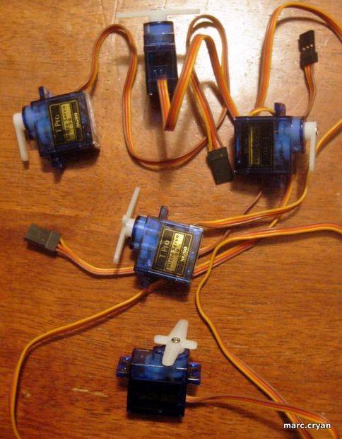
- 5 mini hobby servo motors -- 9 Gram Micro-servos
- About 8 packets of Sugru (or one big pouch)
- Arduino Uno with a Screw Shield
- Battery pack - 4 AA batteries (6V supply)
- Servo proto-shield (from Wendell Robot)
- Controller (from Giant Crane Game)
- L-bracket or metal plumbers strap (cut and bent)
- Screws for servo arms
- Servo adapter/servo connector board (brings digital pins, power, ground)
- Parts list
- Build
- Wire
- Program
- Play!
Outcomes of this project:
- Robot with 5 joints
- Arduino Code which is expandable
- Control and wiring setup
Step 1: Parts
Parts used:
- 5 mini hobby servo motors — 9 Gram Micro-servos
- about 8 packets of Sugru — or one big puch
- Arduino Uno – with a Screw Shield
- Battery pack – 4 AA bats
- Servo proto-shield — from ‘Wendell’ Robot
- Controller — from Giant Crane Game
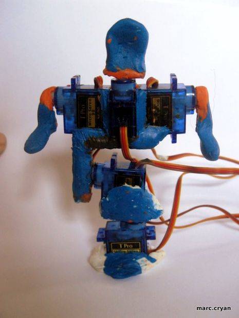
Step 2: Build — Bottom of Robot
The bottom servo will twist the whole robot side-to-side.
The next servo is the waist — it will bend.
Use Sugru as glue and supports — pack Sugru around the servo arms.
NOTE:
Pay attention to the positions of the servo arms as you build.
To determine servo arm/horn position do this:
- What joint is the servo?
- Snap on the servo arm — DO NOT ADD SCREW
- Turn the servo arm all the way to one side — this is either 0 or 180 deg
- Then pull of the servo arm
- Re-align the servo arm so it is how you would want it to be when turned all the way, and stick it on (ex – body twisted all the way to the right)
- Now — Turn the servo arm all the way to the other side — hopefully it will be in the opposite side (ex – body twisted all the way to the left)
- If it is good, then add the screw
- If it is not where you had expected, pull of the arm and re-position halfway to the ideal position
- Turn the servo all the way to the other side
- If the servo is now in an okay spot at both extremes — add the screw.
- Now — it should be like this: 0deg = all the way to one side; 90deg = in the middle; 180deg = all the way to the other side
Step 3: Build — Arms and Head
Using 3 servo motors you can get:
- Head back and forth
- Both arms up and down
More servos will give you more motions; but it gets big and heavy very fast.
But for now – No jumping jacks are ‘YMCA’
Steps:
- Position and attach servo arms
- Cover the servo arms in Sugru
- Use Sugru to stick the motor bodies together
- Add some more Sugru for support
- Cut down the servo arms for the ‘neck’
Step 4: Build — Bracket
An L-Bracket is used to connect the top and bottom sets of servos.
My go-to for light brackets is metal plumbers strap.
- Cut about 5 inches of strap
- Bend a 90deg angle towards the middle
- Layout the servos and bracket to make sure it will all fit together
- Trim or bend bracket to adjust
- Press Sugru onto both sides of the bracket
- Assemble the parts as shown in photos
Step 5: Let it dry
Lay out the robot so that the servos are in the correct positions. This is a little tricky. Check on it every 10min or so until it starts to set-up, tweak as needed.
Letting it cure overnight worked well.
Step 6: Photo shoot
Step 7: Wire it up to Arduino
There are many ways you could wire the servos up to the Arduino. I’ll list exactly what I did here. The important thing is that your Arduino code matches the actual pin connections.
I am using a servo adaptor board made in another instructable — here.
It brings the digital pins on one side, then the power supply; and ground is last.
// attach servos //
servoHead.attach(11);
servoArmR.attach(10);
servoArmL.attach(9);
servoBend.attach(6);
servoTwist.attach(5);
On the servo connectors: orange – communication; Red = power; Brown = ground.
Servo power is supplied by a 6Volt battery pack — this should be able to power the arduino too, but for now the USB is fine.
‘Negative’ side of battery pack should be connected to the arduino ground.
The controller is also from an old project — here.
Here is the wiring to the buttons on the controller and to the Arduino –
Wire the Buttons – Arduino Analog/Digital:Blue – Up (joystick) – A0 / D14
Blue/white – Down (joystick) – A1 / D15
Orange – Left (joystick) – A2 / D16
Orange/white – Right (joystick) – A3 / D17
Green – Left button (arms) – A4 / D18
Green/White – Right button (head) -A5 / D19
Brown – Ground (Arduino) – Ground
Brown/White – 5V (Arduino) – 5V
(note: the analog pins on the Arduino can be used as digital pins)
For more detail: Sugru + Servos = Robot
- What servos are used?
Five 9 Gram micro hobby servos are used. - How is Sugru used in the build?
Sugru is used as glue and structural supports around servo arms and to stick motor bodies and bracket together. - How do you set servo horn positions?
Snap on the horn without the screw, turn servo to one extreme, remove and re-align horn to match that extreme, test the other extreme, and add the screw when extremes align acceptably. - Which Arduino pins are the servos attached to?
servoHead.attach(11); servoArmR.attach(10); servoArmL.attach(9); servoBend.attach(6); servoTwist.attach(5); - How is the servo power supplied?
Servo power is supplied by a 6V battery pack (4 AA); negative of battery pack must be connected to Arduino ground. - How are the controller buttons wired to the Arduino?
Buttons map to analog/digital pins: Up A0/D14, Down A1/D15, Left A2/D16, Right A3/D17, Left button (arms) A4/D18, Right button (head) A5/D19; Brown to ground and Brown/White to 5V. - What bracket is recommended to connect top and bottom servos?
An L-bracket made from metal plumbers strap cut to about 5 inches and bent 90 degrees is used. - How long should Sugru cure before moving on?
Let it start setting and tweak every 10 minutes, and allowing it to cure overnight worked well.