
Summary of STUFFING A 32-PIN CHIP INTO A 28-PIN SOCKET
Summary: Anders Nielsen replaced a 28-pin W27C512 EEPROM with a 32-pin SST39SF010 Flash ROM by exploiting JEDEC-compatible pinouts. He sacrificed the upper half of Flash capacity, jumpers Vcc into the correct pin, added pull-up resistors for write-enable and A16, and used a socket for clearance. Oxidized pins caused intermittent soldering issues. The mod lets the larger Flash work in older 28-pin sockets with minor bodging.
Parts used in the 32-pin-to-28-pin ROM swap:
- SST39SF010 Flash ROM (32-pin DIP)
- W27C512 EEPROM (28-pin DIP) — original target type
- Wire jumper (to connect pin 32 to pin 30 on the Flash chip)
- Pull-up resistors (for write-enable and A16)
- 28-pin socket (to mount/use the 32-pin chip with clearance)
- Soldering tools and solder
- Optional additional socket or spacer for vertical clearance
What’s the difference between a 64k ROM in a 28-pin DIP and a 128k ROM in a 32-pin DIP? Aside from the obvious answers of “64k” and “four pins,” it turns out that these two chips have a lot in common, enough so that it only takes a little bodging to make them interchangeable — more or less.
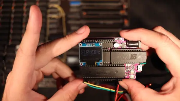
For a variety of reasons revealed in the video below, [Anders Nielsen] use the SST39SF010, a Flash ROM in a 32-pin DIP, in place of the old standby W27C512, an EEPROM in a 28-pin DIP. To deal with those pesky extra pins on the Flash ROM, [Anders] dug into the data sheets and found that thanks to JEDEC standards, almost everything about the pinouts of the two chips is identical. The only real difference is the location of Vcc, plus the presence of a 16th address bus line on the more capacious Flash ROM.
Willing to sacrifice the upper half of the Flash chip’s capacity, [Anders] set about bodging the 32-pin chip to work in a 28-pin socket. The mods include a jumper from pin 32 to pin 30 on the Flash chip, which puts Vcc in the right place, and adding a couple of pull-up resistors for write-enable and A16. Easy enough changes, but unfortunately, [Anders] chose a Flash ROM with heavily oxidized pins, leading to some cold solder joints and intermittent problems while testing. There’s also the fact that not all boards have room for overhanging pins, a problem solved by adding a socket to create a little vertical clearance.
We found this to be a neat little hack, one that should make it a bit easier to use the wrong chip for the job. If you want to see where [Anders] is using these chips, check out his 6502 in an Arduino footprint or the bring-up of an old XT motherboard.
Source: STUFFING A 32-PIN CHIP INTO A 28-PIN SOCKET
- Can a 32-pin SST39SF010 Flash ROM be used in place of a 28-pin W27C512 EEPROM?
Yes, with modifications: jumper Vcc to the correct pin, add pull-up resistors for write-enable and A16, and sacrifice the upper half of the Flash capacity. - What is the main pinout difference between the two chips?
The primary differences are Vcc location and the presence of the A16 address line on the 32-pin Flash. - How is Vcc corrected when using the 32-pin chip in a 28-pin socket?
By adding a jumper from pin 32 to pin 30 on the Flash chip to place Vcc where expected. - Do I need extra components when making the swap?
Yes, you need pull-up resistors for write-enable and A16 and a jumper wire; a socket or spacer may be needed for clearance. - Will the full capacity of the 32-pin Flash be available after the mod?
No, the upper half of the Flash capacity is sacrificed to match the 64k address space of the original chip. - Are there common practical problems when performing this bodge?
Yes, oxidized pins can cause cold solder joints and intermittent issues, and some boards lack room for overhanging pins. - How can overhanging pins be accommodated on a board with limited space?
By adding an extra socket or spacer to create vertical clearance for the 32-pin package. - Why does this trick work electrically between the two chip types?
Because JEDEC standards make much of the pinout identical between the chips, allowing compatibility with minor adjustments.
