Are you a teacher? Do your students leave your classroom and stay out too long? Are you tired of trying to keep track of whether someone is out of the room and how long he/she has been out? If so, then the the Strive For Five Classroom Exit Timer is for you.
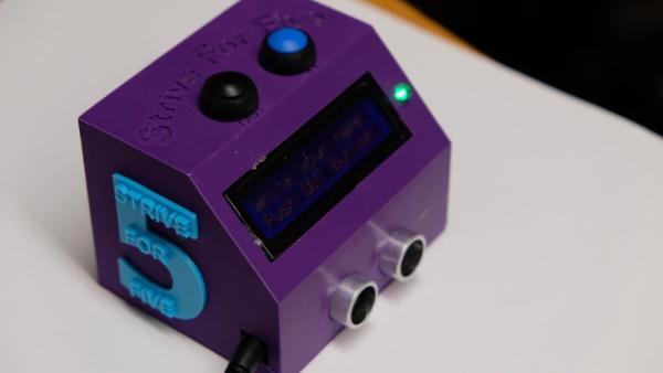
Strive for Five is a timer that teachers can use in their classrooms to keep track of whether or not a student is out of the room and for how long. A student who wishes to exit the classroom simply presses the “out” button and the device indicates that someone is out, while keeping track of the amount of time he/she is out. The student presses the button upon returning to the classroom to stop the timer.
This intractable will teach you how to can make this timer. I have included wiring instructions, the Arduino code, and stl files so you can print your own 3D box for your timer.
Let’s get started!
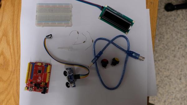
Supplies
Arduino Uno with USB cable
Breadboard
2 buttons
RGB LED – common cathode type
2 1K-ohm resistors
3 220-ohm resistors
Jumper wires
Soldering iron if desired
stl files for 3D printing the case
9V 1A power supply cable adaptor with jack
Step 1: Build Your Circuit
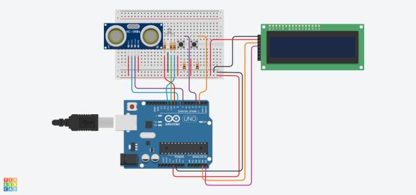
You can begin by building your circuit as shown in the diagram above using a solderless breadboard. Later, you can solder the wires together, once you make sure that it is wired correctly.
Begin by wiring the ultrasonic sensor, making sure that you attach the wires correctly. I used pin 8 as the echo pin and pin 7 as the trigger pin. You may choose other pins, but if you do, you will need to adjust the code accordingly.
Then attach the LCD. I used a 16×2 LCD with an attached I2C backpack. This allows you to use only four pins rather than 16. With I2C, there are only four pins necessary: Ground, VCC (5 volts), SDA (analog pin 4) and SCL (analog pin 5).
Next, attach 2 buttons as shown above. Note the buttons I indicated in the supply list. These will fit the holes I made in the 3D box I designed. I used a pull-down resistor, which causes the buttons to have a value of 0 when not pushed and a value of 1 when pressed. If you use a pull-up resistor instead, you will need to reverse the values in the code.
Finally, attach the RGB LED. I used a common cathode LED and a 220-ohm resistors attached to each of the legs. The long leg is connected to ground. If you use a common anode LED, then you will need to attach the long leg to 5V instead. You will also need to change the values of the brightness because HIGH (or 225) is off and LOW (0) s on in for common anode LEDs. In TinkerCad, you will notice that the positions of the Blue and Green LEDs are reversed on their RGB LED.
Step 2: Upload Your Code
Now, open up the Arduino IDE. Download the code provided and upload it to the Arduino. You will need to install the liqudcrystal_I2C library in order to run the LCD. You can download it here. Make sure that you unzip the file and place the library into the Arduino libraries folder.
After uploading the code, you will first see the LED color change a few times and see a notice that says “Welcome to Science Class.” Feel free to change that line in the code to match whatever class you teach.
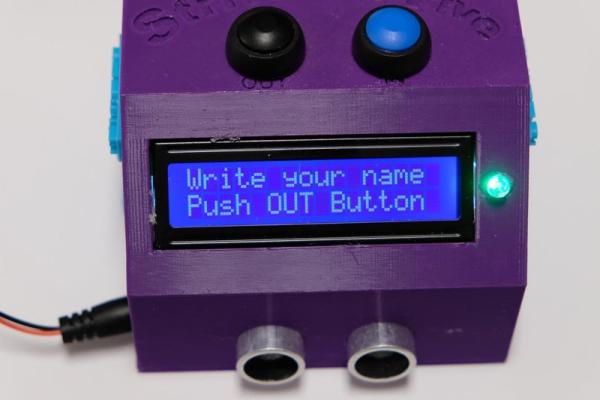
The backlight will then turn off and stay off until someone comes close to the ultrasonic sensor. A green light will stay on letting others know that no one is out of the room. When a student approaches the ultrasonic sensor, the backlight will turn on and instruct the student to sign his/her name on the sign-out sheet and to push the “out” button. This reminds the student of the 5-minute limit and begins the timer. The RGB LED changes from green, to blue, indicating that a student is out of the classroom,. The LCD also states that someone is out and how long that student has been out of the room. Upon returning to the classroom, the student pushes the “in” button to stop the timer. The LCD then displays the amount of time that the student was out of the room in case the teacher would like to record the time. If a student exceeds the five-minute limit, the LCD indicates that there a violation of the five-minute rule and the RGB LED flashes red and green for a few seconds and then resets itself.
Now try it for yourself and see if it works!
Step 3: Soldering
If you want to place the parts into the 3D printed case, you will need to eliminate the breadboard by soldering the wires together.
1) Solder all the ground wires together and connect it to the Arduino ground pin, Don’t forget to include the ground wires for the buttons and RGB LED.
2) Solder all the 5V wires together, and connect it to the Arduino 5V pin. Again, don’t forget to include the wires connected to the buttons.
3) Solder a 1K-ohm resistor to each button and as well as the signal wires. If you will be printing the 3D box, hold off on soldering the buttons so that you can make sure that you allow for the placement of the button through the holes in the box. Otherwise, the buttons may not fit into the box correctly and you will need to resolder it.
4) Solder a 220-ohm resistor to each of the short legs of the RGB LED and attach wires to them to connect to the appropriate Arduino digital pins.
Step 4: 3D Print the Case
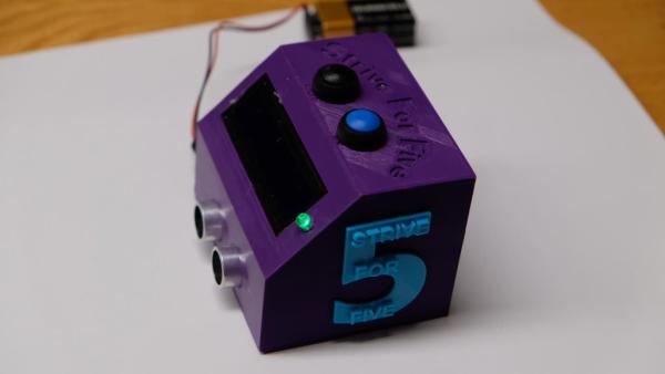
I have attached three stl files if you want to print the case.
I hope you enjoyed this project. Please let me know if you made the timer and send me pictures of your finished project! I hope it helps you keep track of your student’s comings and goings in class!
Source: Strive for Five: Arduino 5-Minute Classroom Exit Timer