Summary of Speech-controlled Game Boy Advance using arduino
This project enables voice control of a Game Boy Advance using an Arduino Uno and BitVoicer speech recognition software. By speaking button names, the system triggers relays to simulate physical presses on the GBA's circuit board. While effective for basic navigation, users should note a 1-2 second latency and occasional misrecognition issues. The build requires soldering components onto a perfboard and carefully modifying the GBA hardware.
Parts used in the Speech-controlled Game Boy Advance:
- Arduino Uno
- Game Boy Advance
- Computer with BitVoicer speech recognition software
- 7 relays (OMRON G5V-1 and Magnecraft W171DIP-7)
- 2 8-pin female headers
- 2 6-pin female headers
- Adafruit electret microphone amplifier
- 4 IC sockets
- Perfboard
- Wire
- Solder and soldering iron
- Tri-wing screwdriver
This is a project I worked on for my electronics class at Pomona College. Thanks to Professor Dwight Whitaker and Tony Grigsby for their help and guidance throughout this project, and credit to Jonathan Wong for the idea for this project!
Also, here’s a list of Instructables I looked at for ideas/inspiration while working on this project:
http://www.instructables.com/id/Speech-Recognition…
http://www.instructables.com/id/Wireless-Audio-Str…
http://www.instructables.com/id/Speech-Recognition…
http://www.instructables.com/id/How-to-modify-your…
How it works
The basic idea of this speech-controlled Game Boy Advance is that you can say the name of a button (left, A, start, etc.) and have the GBA respond as if that button had been pressed. Here’s a quick rundown of how I’ve set it up to work:
1. You say a word into a small microphone (let’s assume you say “start”), and this signal is sent from the microphone to the computer through the Arduino.
2. The speech recognition software BitVoicer sees that “start” is a word it’s supposed to respond to and sends the Arduino the string “start”.
3. The Arduino receives the string and sets the voltage of one digital output pin to HIGH and the rest to LOW. The pin set to HIGH is connected to a relay that is in turn connected to two metal pads on the GBA circuit board that correspond to the start button.
4. Since the pin is set to HIGH the relay switches states, making the two metal pads electrically connected. This electrical connection is what happens when you usually press GBA buttons, so the GBA responds as if the start button was pressed.
I have this currently set up for all buttons except L, R, and select. I chose not to do it for these buttons because they aren’t used quite as often as the other buttons and I wanted to first focus on getting the essential buttons to work. The direction buttons are set to stay on HIGH until you say a new command (equivalent to holding down the button) while the A, B, and start buttons are set to stay on HIGH for 200 ms before switching to LOW (equivalent to pressing the button once). I’ve also programmed a “stop” command that sets all the pins to LOW to stop all ongoing commands.
Issues
Although the speech control works fairly well, there are a few issues to be aware of. For one, there’s a delay of about one or two seconds between when you say a command and when the GBA responds to it. So don’t expect to be playing any games where timing’s important, unless you happen to be really good at thinking ahead and saying commands early! Another issue is that BitVoicer sometimes fails to recognize a command, but this doesn’t happen too often and when it does you usually only need to repeat yourself once or twice. I’ve particularly had trouble with it thinking I said “b” when I was saying “a”. Also, menu navigation can sometimes be troublesome with the current setup: sometimes you’ll scroll through menus really fast since the direction buttons are held down, while at other times you’ll have to alternate between a direction button and the stop command (i.e. “down, stop, down, stop,…”) if you want to keep going in one direction on a menu. Whether you run into these problems or not depends on how the game you’re playing deals with menu navigation. To fix this last problem I’m thinking of eventually adding some code that’ll allow for two commands for each direction button, one that’ll hold it down and one that’ll press it once.
Despite these issues I thought this project turned out fairly well and I really enjoyed working on it. I hope you do too!
Step 1: What you’ll need
Here’s a list of what I used for this project:
- Arduino Uno
- Game Boy Advance
- Computer with BitVoicer speech recognition software (You can download BitVoicer online, after which you’ll need to buy an activation code for US $4.50. This can all be done on the BitSophia site.)
- 7 relays (I used 3 OMRON G5V-1 relays and 4 Magnecraft W171DIP-7 relays. I used two different kinds of relays because I didn’t have seven of either. It shouldn’t matter what kinds you use as long as you have seven, though.)
- 2 8-pin female headers
- 2 6-pin female headers
- Adafruit electret microphone amplifier (here’s the one I used)
- 4 IC sockets (I used these for just the Magnecraft relays because I couldn’t get my hands on any or the OMRON relays)
- Perfboard (At least 20 x 28 holes; I opted for using a perfboard rather than a printed circuit board due to time constraints. Feel free to put everything on a PCB if that’s more to your liking.)
And here’s a few other things you’ll find useful:
- Wire
- Solder and a nice soldering iron
- Tri-wing screwdriver (for opening up the Game Boy Advance)
Step 2: Setting up the circuit elements on the perfboard
Note: The next few steps require soldering, so get your soldering iron out! If you don’t have too much experience soldering, then it might be helpful to look at some Instructables on soldering for advice before diving in.
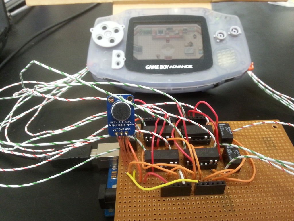
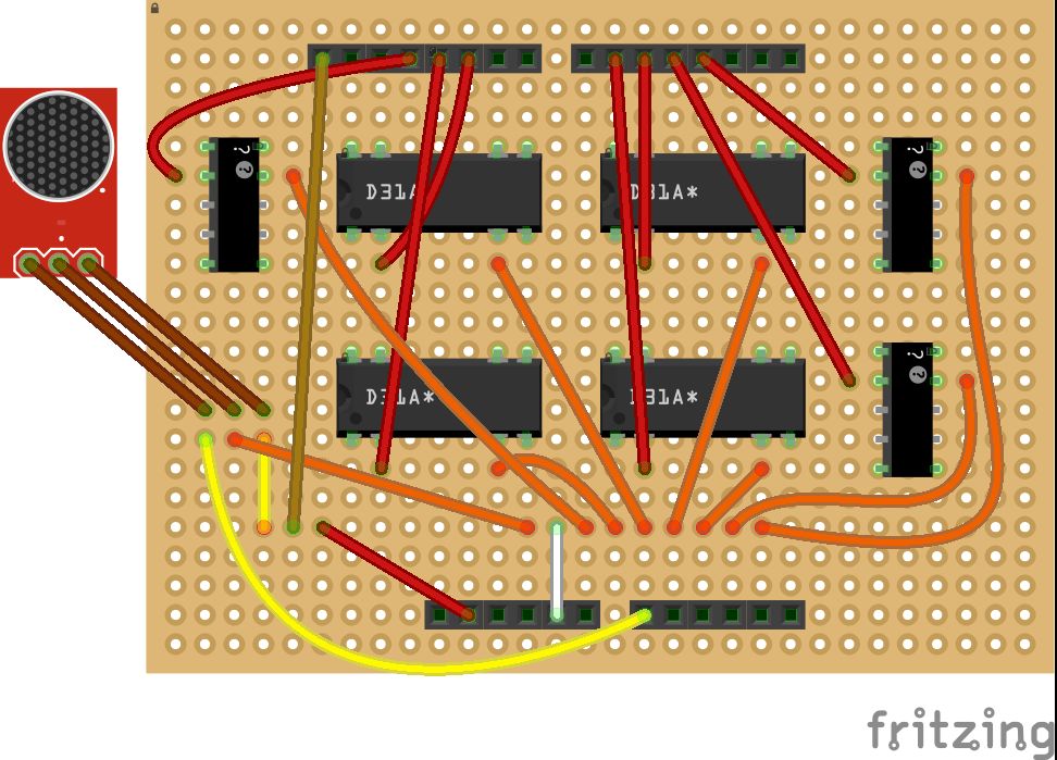
We’ll start by setting up the circuit elements we’ll need on the perfboard. The diagram above shows what we want to have set up when we’re done with this step. Look at this diagram to figure out where each component should be placed. If you hover over the boxes on the diagram you can see notes that’ll help you with setting everything up. Be sure you have the headers at the same relative positions as in the diagram. These headers will plug into the pins on the Arduino, so they have to line up with the Arduino pins (actually they won’t perfectly line up due to spacing of the Arduino pins, but the positioning of the headers in the diagram will give the best possible fit)!
I’d recommend soldering in this order: first IC sockets and headers, then relays. Be careful when soldering in relays. Too much heat can damage them! Then place any relays that you aren’t soldering into their IC sockets, as the wiring we’ll be doing soon might make it difficult to put in these relays at a later time. Be careful about the orientation of the relays. The wiring that’s coming up is dependent upon the relays being oriented as shown in the diagram, so it’ll be easiest if you have your relays oriented the same way.
Step 3: Wiring up the perfboard
Now we want to put in most of the wiring on the perfboard as well as the microphone. This wiring is shown on the diagram above (once again, hover over the diagram to see the notes). Keep in mind that this wiring is based on the pin configuration of the relays I used. If you’re using different relays then you’ll need to look up the data sheets for those and adjust your wire placement accordingly.
The red wires (EXCEPT for the one towards the bottom of the board) have one end soldered next to the input pin of a relay and the other end plugged into a header. The orange wires have one end soldered next to the ground pin of a relay and the other end on the same row as one end from each of the other orange wires. These eight orange wire ends are soldered together in a row along with one end of the white wire. This white wire then plugs into a header (which will go to a ground pin on the Arduino). Once you have these red and orange wires soldered to the board, also solder them to the pin that they’re right next to.
Now let’s look at the wires that interact with the microphone (around the lower left of the board). The leftmost brown wire goes from the microphone output to the board, where it’s soldered to the yellow wire right below it. This yellow wire then goes to a header pin that will go to the A0 pin on the Arduino. The middle brown wire goes from the microphone GND to the board, where it’s soldered to the orange wire that ends up going to ground. The rightmost brown wire goes from VCC on the microphone to the board, where it’s soldered to the short yellow wire. The other end of this yellow wire is soldered to the ochre and red wires next to it. The ochre wire has its other end at a header that’ll go to AREF on the Arduino. The red wire has its other end at a header that’ll go to the 3.3 V pin on the Arduino. This 3.3 V will be the reference voltage for the microphone.
In terms of connecting the brown wires to the microphone, I currently just have mine bent over into place (see picture). This seems to be working fairly well for me so far. My brown wires are long enough that they hold the microphone above the other wires on the board, which makes it easier to talk into the mic.
Step 4: Opening up the Game Boy Advance
You now want to connect the perfboard to the GBA, but you can’t do that if you don’t have access to the GBA’s circuit board! To get access to the circuit board you’ll need to open up the GBA. I found this guide really helpful while doing this. We don’t want to completely dismantle the GBA, though, so don’t go past step 9 of this guide. Be careful when handling the inner components of the GBA. Don’t pull the ribbon wire too hard and try to avoid touching the circuit board as much as you can.
After opening up the GBA you’ll have a bunch of screws and plastic pieces like the L and R buttons that you’ve removed. I haven’t put most these back on the GBA in any way and I’ve just put them all in a plastic bag for safekeeping. As for the direction pad, start/select pad, and A and B buttons, I just keep those upside down where they would normally go as a rudimentary means of preventing dust from getting into the GBA (as seen in the first picture in this Instructable).
For more detail: Speech-controlled Game Boy Advance using arduino
- How does the system interpret voice commands?
The microphone sends audio to the computer where BitVoicer identifies the word and sends a string like start to the Arduino. - Can I use any type of relay for this project?
Yes, you can use any relays as long as you have seven, though you must adjust wiring based on their data sheets. - What is the delay time when using voice commands?
There is typically a delay of about one or two seconds between saying a command and the GBA responding. - Which buttons are not currently supported by this setup?
The L, R, and select buttons are excluded because they are used less frequently than the essential buttons. - How are direction buttons handled differently from A or B buttons?
Direction buttons stay HIGH until a new command is given, while A, B, and start buttons stay HIGH for only 200 ms. - What happens if BitVoicer fails to recognize a command?
You usually need to repeat yourself once or twice, though it sometimes mistakes b for a. - How do you stop all ongoing commands?
Saying the word stop sets all pins to LOW to halt any active signals. - Why was a perfboard chosen over a printed circuit board?
The author chose a perfboard due to time constraints but notes that a PCB is also acceptable. - What voltage is used as the reference for the microphone?
The 3.3 V pin on the Arduino serves as the reference voltage for the Adafruit electret microphone amplifier. - Is it necessary to completely dismantle the Game Boy Advance?
No, you only need to open it up enough to access the circuit board without fully dismantling the device.