
Summary of Specan – A reboot of the W7ZOI/K7TAU spectrum analyzer
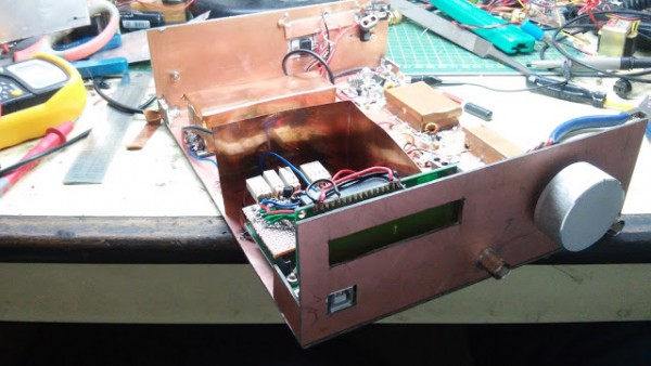
This article describes a DIY spectrum analyzer named "Specan," built for under $100 using a superhet radio modified with a log amp and an Arduino. It operates up to 70 MHz, offers two resolution bandwidths (300 kHz and 1 kHz), and features tunable steps of 100 Hz. The device displays data via a PC or a built-in LCD, aligning its own filters during operation, and is released under the GPL v2.0 license.
Parts used in Specan:
- Superhet radio
- Log amp
- Arduino
- PC
- Built-in LCD
- Low pass filter (LPF)
(A better, higher resolution diagram can be downloaded here: from my G Drive)
If you don’t want to read this long long write-up, here is a summary:
If you don’t want to read this long long write-up, here is a summary:
- This spectrum analyzer costs less than $100 to make.
- It is just a superhet radio that has a log amp where the speaker should have been.
- You can hack it. It has an Arduino.
- Works as well as a commercial spectrum analyzer. In some ways, even better.
- Works only upto 70 MHz (good enough for HF work, for VHF just remove the LPF)
- It has just two resolution bandwidths : 300 KHz and 1 KHz. Quite enough for our kind of radio work.
- You have to align the filters. Easily done, but still, you have to do it.
- You use parts of the specan to align other parts. In this sense, it aligns itself!
- Works with a PC instead of an oscilloscope for display.
- It has a built-in LCD for quick readings
- +15dbm IIP3, spur free dynamic range of 80 db at 1 KHz resolution, 70 db at 300 KHz.
- Tunable in 100 Hz steps.
- All under GPL v2.0 license.
Why do I need a spectrum analyzer?
Most of the homebrewers have a very basic measurement setup. Often we get by with just a VOM, an RF probe and maybe a frequency counter. The more ambitious experimenters aspire to acquire an oscilloscope – an expensive item. These instruments are quite useful but not enough for RF tinkerers.
Often times, we homebrewers end up using the following:
- An RF Probe
This costs nothing to make. Coupled with a dummy load, it can provide reasonable measurement of power levels of RF signals from a milliwatt upwards. But it offers no insight into the frequency of the RF signal - A Frequency Counter
For a few dollars, we can program a PIC and an LCD display to display the frequency of an RF signal. However, the frequency counter does a very poor job. Imagine feeding a diode modulator’s output to the frequency counter. What would it read? the Modulation frequency? The carrier frequency? The upper side-band or the lower side-band? Your guess is as good as mine. When it comes to RF signals that have multiple frequency components like most of our RF circuits do, the frequency counter becomes useless. At best, you can use it to measure the frequency of your new VFO’s oscillations, but that’s about all you can do with it with any accuracy. - The Oscilloscope
A few hundred dollars buys you an oscilloscope that can show you the exact waveform. Well, nearly exact. You could look at a sinewave and say that it is clean or not. But, consider this, a power amplifier with a second harmonic that is just 40 db down (and hence illegal to use on the air) will not register on the oscilloscope waveform at all. That is a variation of only %1 of the waveform from its expected shape. You won’t see that on your beloved ‘scope. You will more!
For More details: Specan – A reboot of the W7ZOI/K7TAU spectrum analyzer
- How much does it cost to make?
It costs less than $100 to make. - What frequency range does it cover?
It works only up to 70 MHz. - Does it have variable resolution bandwidths?
Yes, it has just two resolution bandwidths: 300 KHz and 1 KHz. - Can I use an oscilloscope for display?
No, it works with a PC instead of an oscilloscope for display. - Is there a built-in display option?
Yes, it has a built-in LCD for quick readings. - What are the tuning step sizes?
It is tunable in 100 Hz steps. - How do I align the filters?
You have to align the filters easily by using parts of the specan to align other parts. - What is the licensing model?
All designs are under GPL v2.0 license.
