Summary of Spaceship Control Panel – Laser Cut Arduino Toy
This article details the creation of a custom Arduino-based spaceship control panel toy for a child's birthday. The author describes the design process, from initial sketches to laser-cutting acrylic and MDF parts. It highlights challenges faced during assembly, offers advice on using WS2812B LEDs instead of CD4017 counters for easier programming, and provides a comprehensive list of tools and materials required to build the interactive project featuring buttons, lights, and sound.
Parts used in the Spaceship Control Panel:
- Arduino Mega 2560 R3
- Mega Sensor Shield V2.0 for Arduino
- Female/female Dupont cables (100 pcs)
- LEDs (3mm and 5mm)
- Male header pins
- PCB strip board
- 16-pin DIP IC sockets (4 units)
- CD4017BE decade counter chips (4 units)
- Red illuminated LED switches with flip covers (2 units)
- Single linear 10k slide potentiometers (2 units)
- Green square illuminated momentary pushbuttons (2 units)
- 3-pin 2-position on/on flip switches (6 units)
- Security lock key switch (DPST or DPDT type)
- SPST on/off rocker switch
- Piezo buzzers (2 units)
- MAX7219 LED Dot matrix 8-Digit Digital Display Control Module
- Single linear rotary 10k potentiometers (2 units)
- Rotary knob covers (2 units)
- Resistors (180/200 ohm, 150 ohm, 100 ohm)
- 9v snap-on battery connector cable
- 4-slot AA-battery holder
- Acrylic sheets (5mm and 2mm thickness)
- MDF (6mm thickness)
A few months ago I decided to become a member of the local maker space, since I’ve been wanting to learn the tools of the maker trade for ages.
I had a tiny bit of Arduino experience and a had taken a Fusion-course here on Instructables. However I had no experience with a lasercutter, nor with any sort of intermediate Arduino programming or components besides the standard LED or simple sensor.
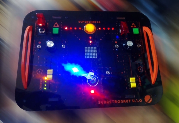
Since my nephew’s 6-years birthday was coming up in a few months I decided that I wanted to make him a present. Since he loves anything space-related (especially if it contains buttons and lights) I came up with the initial idea of making him a simple Arduino-based toy with some LED’s, buttons, a speaker, sliders etc.
So I trawled the internet for tutorials on simple Arduino toy tutorials to get inspired by, but I couldn’t quite find exactly what I was looking for. Jeff High Smith’s amazing spaceship toy and Duncan Jauncey’s remix of it were great inspirations, but were a bit too big a mouthful for me since I was lacking: a) Enough experience to build it, b) Enough time to gain the experience and c) I wanted the project to be controlled only by an Arduino to make it simpler (and cheaper) than having to interface with e.g. a Raspberry Pi or similar. Bob Lander’s beautiful little control panel toy, was also an inspiration, but I wanted to build something with a bit more interactivity.
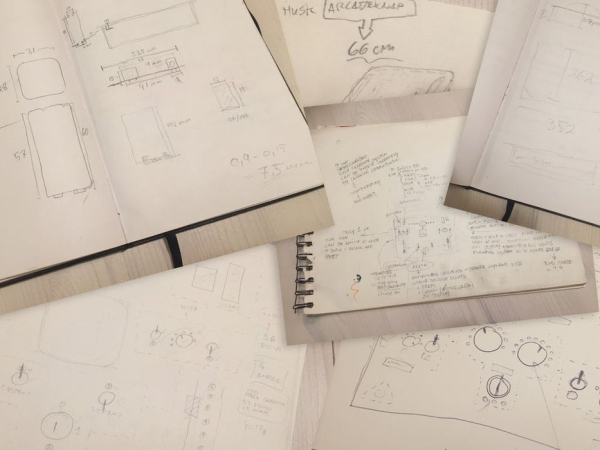
So I started sketching down a few ideas for the control panel until I reached a look that I was happy with.
With the initial design in place (well – sketched out rather quickly on a piece of paper at least) I was ready to move on to actually figuring what it would take to build this – how many and which parts I would need, which Arduino controller to use etc.
WORD OF ADVICE…
… for those that want to venture into the journey of building this: Using the 4017 decade counters is an unnecessarily complicated way to control the LEDs. If you want to make your own version, I’d highly recommend using something like WS2812B (or similar) LEDs, as it will make controlling the LEDs a lot easier (for example using the FastLED library).
Another fellow Instructable member has also discovered some discrepancies between the schematic and the code (with certain I/O pins in the code not corresponding to the shown schematic). I will try to make an updated version of the schematic as soon as I have time. In the meantime, use the code as the basis for the I/O pin setup (not the schematic).
Step 1: Structure of This Tutorial
Now that I had an overall idea of what the spaceship control panel should look like, and having decided to make it relatively simple, I was certain that actually building it would be a breeze…!
Well… turned out the breeze became more of a, well if not a storm, then at least a gale! It was somewhat more difficult than first expected.
The project ended up taking close to three months of sparetime hours, and I only finished the last bit of coding the day before my nephew’s birthday!
However, the build process was a great and fun (and only sometimes frustrating) learning experience with tons of trial and error and things that I would do differently, were I to build it again.
Most steps in this tutorial therefore will each have two sections:
- A “Long Read” section for the patient reader, where I describe my process, thoughts and (likely) mistakes in detail.
- A “Tl;dr” section for the more impatient reader, where I get to the point a bit quicker, and present a recipe to follow (revised by learning from my mistakes).
Enjoy the ride and please feel free to ask questions!
Step 2: Tools and Materials
With my sketch in hand, I could start figuring out how many LED’s, buttons and other stuff I needed.
LONG READ
Since my sketch contained a lot of LED’s (42 including the lit buttons), it was clear that I needed to go for an Arduino Mega. However even using the Mega, there still weren’t enough I/O-pins to accomodate for all of the LED’s, buttons, piezo buzzers and potentiometers.
So I once again trawled the internet for tips on how to control multiple LED’s with just a few I/O-pins and ended up deciding on the “CD4017 decade counter” after reading this neat tutorial.
If I were to make an updated version I would definitely replace most of the LED’s with something like the WS2812B-type LED’s since they are a lot easier to chain, program and play around with. But since I did not know that by the time of the build, this tutorial will still focus on using the CD4017-method.
I also didn’t yet have a clear idea of what the circuit would look like, so I wanted to make sure that I’d be able to disconnect and reconnect wires and components along the way. I therefore chose to make (almost) all of the connections between the components and the board using female/female dupont cables and male header pins.
To make connecting the components to the arduino via the dupont cables easier, I decided to buy a sensor shield for the Mega.
As for the rest of the tools and materials, you can find them below.
TL;DR
Tools:
- Laser Cutter.
Our makerspace has a Universal Laser Systems VLS 3.50 45W which I used for cutting and engraving the acrylic, and a big no-name chinese 120w laser that I used for cutting the MDF. You could quite easily cut the box and the acrylic using standard power tools, however for the engraving on the acrylic/paint the laser is to prefer. - Soldering iron.
- Hot glue gun (optional, but nice to have)
- Screwdriver set.
- Countersink bit.
- Drill bits 2mm-3mm or similar.
- Drill driver (any will do, but a bench drill press will make it easier).
- Masking tape
- Clamps
- Caliper
- A variety of small pliers
- Adobe Illustrator ($$) or Inkscape (free) – or any other vectorbased drawing software.
- Autodesk Fusion 360 (optional) – for designing the case.
Materials
For the case and assembly:
- Acrylic sheets, 5mm thickness. Preferably cast acrylic (since it doesn’t melt and remerge as easily as rolled acrylic does when laser cut).
- Acrylic sheet 2mm.
- MDF, 6mm thickness.
- Spray paint, I used:
- Molotow Urban Fine-Art Artist Acrylic – dare orange. For the faceplate graphic details and the handles.
- Molotow Urban Fine-Art Artist Acrylic – signal black. For the case and the faceplate.
- A generic non-acrylic based black for the 2mm protective acrylic sheet.
- Screws – 2.5 x 13mm (or similar – diameter should not exceed 4 mm.)
- Standard (PVA) wood glue (for gluing the wooden case)
- Contact adhesive or acrylic adhesive (for gluing the 2 mm protective acrylic sheet to the bottom of the faceplate).
- Multimeter (optional, but super useful for finding shorts, testing diodes and general continuity testing).
Electronics:
- Arduino Mega 2560 R3
- Mega Sensor Shield V2.0 for Arduino Mega
- Dupont cables female/female (100 pcs. should be enough). Choose (at least) 30 or 20 cm in length – 10 cm will be too short.
- A whole bunch of LEDs – both 3mm and 5mm.
- Male header pins
- PCB strip board
- 4x 16-pin DIP IC socket (for mounting the decade counters)
- 4x CD4017BE decade counter chips
- 2x Red Illuminated LED switch w. flip cover
- 2x Single linear 10k slide potentiometers
- 2x Green square illuminated momentary pushbuttons. Please note!!: The buttons linked to are NOT lit by LED’s. They are incandescent and will not light up when connected. To make them light up, you will need to desolder the incandescent bulb inside and replace them with a 3mm LED.
I tried ordering some other similar buttons that claimed to be lit by LED, but alas – when they arrived they turned out to also be incandescent. - 6x 3-pin 2-position on/on flip switches
- 1x Security lock key switch (DPST or DPDT type).
- 1x SPST on/off rocker switch
- 2x Piezo buzzers
- 1x MAX7219 LED Dot matrix 8-Digit Digital Display Control Module
- 2x Single linear rotary 10k potentiometers
- 2x Rotary knob cover for the potentiometers
- 22x 180 or 200 ohm resistors
- 11x 150 ohm resistors
- 14x 100 ohm resistors
- 1x T-type “9v” snap-on battery connector cable
- 1x 4-slot AA-battery-holder
Step 3: Measuring Parts and Test-fitting
LONG(-ish)READ
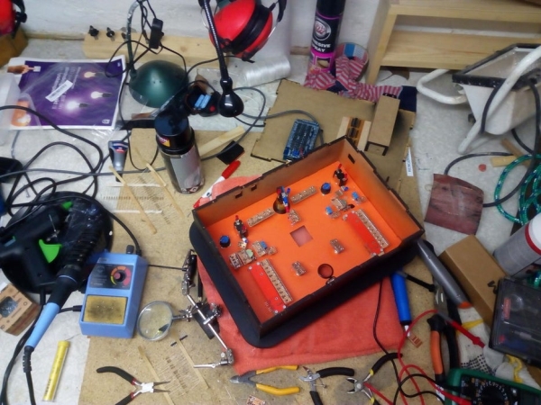
With all of the parts in hand, I could now start measuring each of the individual components to make sure that when I began designing the final design in Illustrator or Inkscape, all of the parts would fit and none of them would overlap on the bottom side of the faceplate.
Especially the key switch was very deep, and thus the final depth (or height, however you wanna put it) of the box would need to accommodate for this, and take this into account when placing the internal components in the case (such as the Arduino Mega, the decade counters etc.).
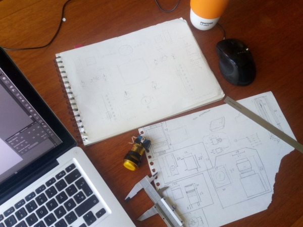
I then produced a simple vector drawing in Illustrator depicting all of the different component diameters/widths, put a 5mm acrylic test piece in the laser cutter, and cut it out.
Having made sure that all of the components fit snugly into their respective holes/slots I then proceeded to draw each of the components in Illustrator (see photo) to make it easy to use in the the final design.
TL;DR
- Measure all of your components using calipers.
- Use the measurements to produce a vector test file with all button/component sizes in Illustrator.
- Cut out the test file on 5mm acrylic on the laser cutter.
- Use the test piece to see if all the components fit snugly.
- If necessary, adjust the hole sizes in the vector file and make a new test piece with the revised sizes.
- Using the final measurements, make a new Illustrator file and draw in all of your components in the correct scale.
- OR don’t do any of the above. I will provide the final vector-file in the next steps, if you just want to use that.
Step 4: Designing the Case
With all of the component measurements in place I could now begin designing the control panel case.
LONG READ
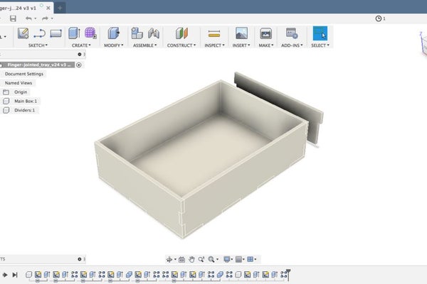
For some reason I decided to make this process a lot harder for myself than necessary and chose to make a parametrically defined finger jointed case in Fusion 360. Well – to be honest, really I just wanted to learn Fusion 360 better, so it wasn’t entirely the decision of a madman, but I could have much more easily used the (quite excellent) MakerCase tool and be done with it.
Instead I chose to follow The Hobbyist Maker’s parametric finger jointed box tutorial, which I can highly recommend, if you want to getter better at 3D parametric design. However making a full 3D model for a design as simple as mine is a bit overkill, since you’ll have to export each surface as a 2D vector drawing afterwards anyway, so you might as well just make it in Illustrator to begin with.
Either way, I continued in Fusion 360 until I was happy with the design. Since I knew (well, hoped at least) my nephew would be carrying this thing around a lot, I wanted to make it easy to for him, by adding some handles. The handles are part of the wooden case and protrude through the acrylic faceplate, providing grip and helping lock the case in place.
With the design in place I exported all of the parts from to 2D .dxf vector files, using the “simple sketch” method described in Taylor Sharpe’s Instructable.
I then modified the dxf files in Illustrator and added a small hatch for accessing the battery compartment and holes for connecting to the Arduino Mega (that I’d also measured in the previous step). I also added a hole for an on/off switch for the sound on the side of the case, and little drill holes on the bottom.
The final drawings for the case are attached to this step (in .ai, .svg, and .pdf format), while the design of the faceplate is coming up in the next steps.
TL:DR
- Use MakerCase to make your basic finger jointed box for the case.
- Modify the MakerCase vector files in Illustrator to fit your needs – remember to add a hatch for the battery and holes for the Arduino ports.
- OR just download the plans attached to this step.
Source: Spaceship Control Panel – Laser Cut Arduino Toy
- What is the recommended alternative to CD4017 decade counters for controlling LEDs?
The author recommends using WS2812B LEDs with the FastLED library as they are much easier to chain and program. - Which Arduino controller was selected for this project and why?
An Arduino Mega 2560 R3 was chosen because the standard number of I/O pins was insufficient for the 42 LEDs, buttons, and sensors required. - How should one handle discrepancies between the schematic and code?
Users should use the code as the basis for the I/O pin setup rather than the schematic, as some pins in the code did not match the shown diagram. - What type of acrylic is preferred for laser cutting the case?
Cast acrylic is preferred over rolled acrylic because it does not melt and remerge as easily when cut by a laser. - Can the provided pushbuttons be used without modification?
No, the linked pushbuttons contain incandescent bulbs; users must desolder the bulb and replace it with a 3mm LED to make them light up. - What tool was used to cut the MDF material for the project?
A big no-name Chinese 120w laser cutter was used to cut the MDF, though standard power tools could also work for the box structure. - Why were female/female dupont cables chosen for connections?
They were chosen to allow components to be disconnected and reconnected easily during the building and testing process. - What software options are suggested for designing the vector files?
The author suggests Adobe Illustrator or Inkscape for vector drawing, and Autodesk Fusion 360 for optional 3D case design.