You probably know the game of flashlight-tag. You just run around in the dark on a campsite. You hold your flashlight and try to shine it on one of the other kids, without the other kids shining their lights on you.
I wanted to make this game electronic. The Arduino is my first choice, but would be a bit expensive. I would need one Arduino for each player. The next clip from “Make:” gave me the idea of using a cheap ATtiny:
I want the thing to register a “hit” and show this for a couple of seconds and count the number of “hits”. That is all it has to do.
Step 1: What do you need
You will need for the PCB:
- 1 ATtiny45
- 1 LED
- 1 resistor to go with the LED
- 2 10 K resistors
- 1 pushbutton
- 1 switch
- 1 light sensitive resistor
- 1 battery (3V button-cell)
To make the PCB:
- 1 blank PCB
- Etching solution
- overhead-foil
- degreaser
- solvant
- sharpy
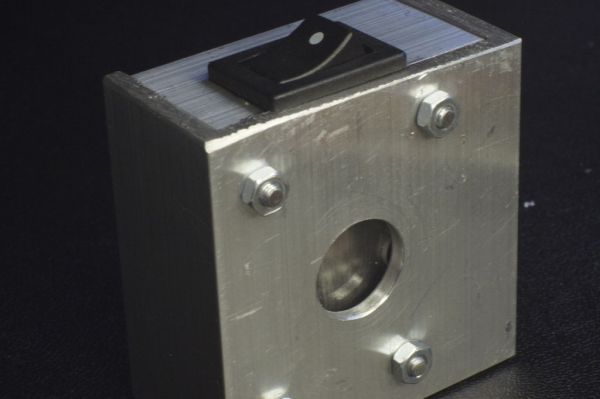
To make the housing:
- aluminum
- clear acrylic material
- nuts and bolts
- sheet of plastic
Tools:
- Computer with
- Arduino software
- Fritzing software
- attiny45_85.zip file
- Arduino board
- breadboard
- jumping-wires
- 10 uF capacitor
- laserprinter
- drill (0,8 – 1 mm)
- drill 3 mm
- drill 20 mm
- soldering tools
- Iron (you know the thing to iron your clothes)
- super-glue
- foam-tape
Step 2: Wire up the breadboard
To make the unit that the players will wear, we first design it on a breadboard.
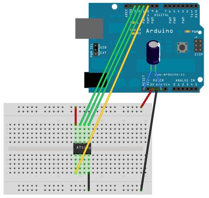
First we put the ATtiny in the breadboard. To program the chip, we need to wire it up to the Arduino. (Look at the drawings to see the numbers of the pins on the ATtiny)
- Pin 1 (This Pin is marked with a point on the ATtiny) goes to Pin 10 on the Arduino.
- Pin 4 goes to GND (ground)
- Pin 5 goes to Pin 11 on the Arduino
- Pin 6 goes to Pin 12 on the Arduino
- Pin 7 goes to Pin 13 on the Arduino
- Pin 8 goes to +5V
- Next we need to put the 10uF capacitor between the Reset-pin and the GND on the Arduino. (The line on the capacitor shows the wire that should go in the GND. Do not mix this up: capacitors can blow up if you turn it around)
If you want, you can also wire up the rest of the parts, but you don’t have to.
I added the Fritzing file for you to check out how to wire up the breadboard.
 zaklampsensor2.fz277 KB
Step 3: Uploading the software
To upload the program to the ATtiny, we need to use the Arduino. The Arduino needs to run the special software from MIT. (http://hlt.media.mit.edu/?p=1229)
Installing the ATtiny support:
- Download: attiny45_85.zip
- Locate your Arduino sketchbook folder (you can find its location in the preferences dialog in the Arduino software)
- Create a new sub-folder called “hardware” in the sketchbook folder.
- Copy the attiny45_85 folder from the attiny45_85.zip to the hardware folder.
- Restart the Arduino development environment.
To turn the Arduino in a programmer we need to run the ArduinoISP sketch:
- Run the Arduino development environment.
- Open the ArduinoISP sketch from the examples menu.
- Select the board and serial port that correspond to your Arduino board.
- Upload the ArduinoISP sketch.
Next we can upload the sketch (program) shown below to the ATtiny:
- Select “ATtiny45 (w/ Arduino as ISP)” or “ATtiny85 (w/ Arduino as ISP)” from the Tools > Board menu (leave the serial port set to that of your Arduino board).
- Upload the sketch.
You’ll probably get the following message, but don’t worry, the upload should have worked anyway:
avrdude: please define PAGEL and BS2 signals in the configuration file for part ATtiny85
avrdude: please define PAGEL and BS2 signals in the configuration file for part ATtiny85
If you get an other error, just try again that just might work.
If you did the complete electronics on your breadboard in the previous step, it should work now. This means that if you turn off the lights, than put power on your breadboard, the LED will blink when you shine a light on the sensor. If you push the button, the LED will flash as many times as the sensor was lighted.
[box color=”#985D00″ bg=”#FFF8CB” font=”verdana” fontsize=”14 ” radius=”20 ” border=”#985D12″ float=”right” head=”Major Components in Project” headbg=”#FFEB70″ headcolor=”#985D00″]
- 1 ATtiny45
- 1 LED
- 1 resistor to go with the LED
- Arduino board
- breadboard
- jumping-wires
[/box]
For more detail: Flashlight tag using an Arduino board