Summary of Smartphone Controlled Cat Laser
This project demonstrates how to build a smartphone-controlled laser tower using an Arduino board and the Blynk app. It serves as an educational introduction to microcontroller programming, allowing users to wirelessly operate servos and a laser module via Wi-Fi. The design prioritizes simplicity and low cost, utilizing a lightweight structure made from taped servos and a repurposed yogurt pot enclosure.
Parts used in the Smartphone Controlled Laser Tower:
- Arduino board with 2 or more PWM pins
- 2 x Micro Servos (Tower Pro)
- 3V-5V Laser Module
- NPN Transistor
- Jumper wires (preferably different colors)
- Smartphone
- Yoghurt pot enclosure
- Small breadboard (Optional)
- Wifi Shield (Optional)

I’ve been wanting to start exploring the world of microcontrollers and programming for some time now, so I came up with this simple project which uses an app called “Blynk” to allow you to wirelessly control an Arduino board through your wifi. Now obviously the end result isn’t the most practical device you’ll ever build, but this was a great way for me to learn the fundamentals of programming Arduino and it can help you to learn too.
I’ve tried to arrange this project in an easy-to-follow format so it’s ideal for someone who knows nothing about Arduino, but there’s a lot of room for tweaking and improvement in my code that would allow more advanced users to get some use out of this project too.
This is a project that’s been done before a few times, but I wanted to add something new by giving the system remote control functionality.
Step 1: Components Needed

This project can be completed for a very low price, I found a starter kit for Arduino that had everything you’ll need for this project for £20/$25 excluding one servo.
- Any Arduino board that can support 2 servos (I believe any Arduino board will work, just check it has 2 or more PWM pins)
- 2 x Micro Servos (I used tower pros, I bought 30 for about £30)
- A 3V-5V Laser Module
- NPN Transistor
- A few lengths of jumper wire, preferably in different colours to help you distinguish them
- A smartphone
- An enclosure – I used a yoghurt pot because at the right angle it’s totally disguised
Optional:
- A very small breadboard would be useful for wiring if your laser is only going to be a temporary thing
- A Wifi Shield would allow you to use the laser while it’s not connected to a computer, but it would also require a battery
Step 2: Wiring
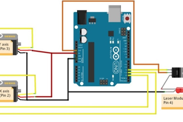
The diagram I’ve attached should be all you need to wire up the Arduino.
The servos both need a positive and negative power supply to move, as well as a signal wire which goes into one of the digital PWM pins. The Arduino drives the servos by outputting a signal that oscillates between a high and low voltage (5V and 0V), It tells the servos the exact position they need to be in via the pulse width of the signal, meaning that the time between the signal being turned on and off corresponds to a position that the servo can move to. Arduino boards can easily do this using the Servo.h library, and all that we need to specify is the angle in degrees that the servo should move to.
The transistor is used simply because the laser may draw a lot of power depending on what module you choose. If we were to wire the positive end of the laser directly to the digital output pin on the Arduino, it may work but it also may result in that pin being overloaded with too high a current. The 3.3V pin on the Arduino goes into the collector of the transistor (I would recommend checking the datasheet of your transistor to verify which pin is which – simply search for the product code printed on the transistor and you should find it easily), and the signal pin goes into the base. The emitter is wired directly to the positive terminal of the laser module, and the negative terminal goes to GND on the Arduino board. Note that the laser module does not need a resistor like an LED would, because it already has resistors inside of it. Make sure that your laser module is actually a module, if you’ve got a simple laser diode it might not have a resistor factored into its design.
The Arduino will need to be plugged into the PC via the USB cable, but if you plan to use a battery then you won’t need to (I’ll go into this later).
Step 3: Building the Laser Tower
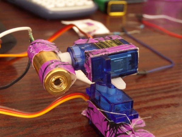
As you’ve probably already noticed, the actual tower was very simply made just by taping together two servos and the laser. I chose to go with this ultra-lightweight design over something more sturdy so that the servos wouldn’t need to work as hard and could be faster and more responsive. One servo must function as the x-axis, sweeping in an arc while staying parallel to the floor. Another must be used as the y-axis, going up and down. I think most people will find this step really easy, and I’d encourage you to experiment to try different configurations, and maybe something a bit more sturdy!
I taped this tower to the lid of the yoghurt pot so that it sat upside-down, and cut a hole in the back of the pot to allow the beam to shine through. I also cut a discrete hole near the base for the Arduino to be plugged in.
Read more: Smartphone Controlled Cat Laser
- How does the Arduino control the servo positions?
The Arduino drives servos by outputting a signal oscillating between 5V and 0V, where the pulse width corresponds to the specific angle in degrees. - Why is an NPN transistor required for the laser?
The transistor prevents the digital output pin on the Arduino from being overloaded by the high current the laser module might draw. - Does the laser module need an external resistor?
No, the laser module does not need a resistor because it already has resistors built inside, unlike a simple laser diode. - What is the function of the two servos in this build?
One servo acts as the x-axis sweeping parallel to the floor, while the other acts as the y-axis moving up and down. - Can this device run without a computer connection?
Yes, if you use a Wifi Shield and a battery, the laser can operate independently without being plugged into a PC. - What is the purpose of the yoghurt pot in this project?
The yoghurt pot serves as a disguised enclosure; a hole is cut for the beam to shine through and another for the Arduino plug. - Is the Blynk app necessary for this project?
Yes, the article states the project uses the Blynk app to allow wireless control of the Arduino board through wifi. - What is the recommended way to power the servos?
The servos require a positive and negative power supply connected to the Arduino along with a signal wire on a digital PWM pin.