Summary of Smart Washroom: Experience Hands-Free Lighting with IR Sensors
This project uses an Arduino Uno with two FC-51 IR sensor modules to detect entry and exit of a single occupant and automatically switch a bathroom light via a 5V relay driven through a BC547 transistor. The Arduino reads sensors on pins 7 and 8, updates a count variable, and drives pin 9 high when count equals one to energize the relay and power the 230V lamp; construction is on a PCB with specified connectors for 5V and AC mains.
Parts used in the Automated Washroom Light:
- Arduino Uno (Board 1)
- ATmega328P microcontroller (on Arduino Uno)
- FC-51 IR sensor module (Module 1)
- FC-51 IR sensor module (Module 2)
- BC547 NPN transistor (T1)
- 5V electromechanical relay (sugar cube) (RL1)
- Light bulb or tube light (230V AC load)
- Printed circuit board (PCB)
- Connectors CON1 (5V DC), CON2 (230V AC input), CON3 (light fixture)
- Wiring for Vcc, Vout, GND of sensor modules
- Jumpers/traces for Arduino pins 7, 8, and 9
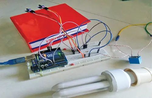
This Arduino Uno and IR sensor-based system automatically controls the lighting in a bathroom connected to AC mains power. The IR sensors detect when a person enters or exits the room. Upon detection of entry, the light bulb or tube light is immediately switched on. When the sensors no longer detect a presence, the lighting will automatically switch off. This helps conserve electricity by preventing the light from remaining on unintentionally after use of the bathroom. The prototype created by the author is depicted in Figure 1.
Circuit and working
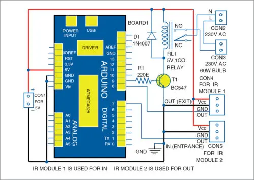
The circuit diagram for the automated washroom lighting system is presented in Figure 2. At the core is an Arduino Uno microcontroller (Board 1). A BC547 transistor (T1) acts as a switch, controlled by the Arduino. Infrared sensor modules (Module 1 and Module 2) detect movement and feed those readings to the Arduino. A relay (RL1) handles switching the actual light on and off when triggered by the Arduino. Together, these components allow the Arduino to monitor the IR sensors and toggle the lamp connected to the relay accordingly.
Infrared sensor
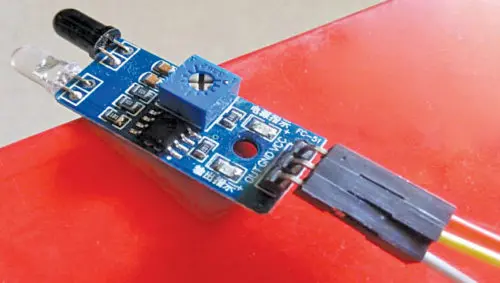
As shown in Figure 3, the project utilizes low-cost infrared (IR) motion sensors known as FC-51 sensors to detect when a person enters or leaves the washroom. Specifically, it employs two pairs of these IR sensor modules, which are commonly used in applications that require objects or movement to be sensed.
The FC-51 sensors function by emitting infrared light and looking for reflected infrared radiation. When an object such as a person enters the detection range, it causes a change in the reflected IR pattern that the sensor can identify. In this setup, one pair is positioned at the entry point while another pair is at the exit. This dual detection allows the Arduino to distinguish someone entering versus exiting for automatic light control purposes.
Each IR sensor module contains three pins – Vcc, Vout, and GND. The Vcc pin provides power and is connected to the Arduino Uno’s 5V pin to receive the 5V DC supply. The GND pin is wired to the Arduino’s common ground.
The critical Vout pin acts as the sensor’s output. For IR Module1, Vout connects to digital pin 8 on the Arduino. IR Module2’s Vout connects to digital pin 7.
When motion is detected, the Vout pin outputs a low (0V) logic level. Otherwise, it outputs a high (5V) level. By reading the digital states of both sensor modules via their Vout pins, the Arduino can determine if someone is entering or exiting based on which signal changes state. Specifically, a low signal on the entry sensor pin followed by a low signal on the exit sensor pin indicates movement into the room, whereas the reverse order corresponds to movement out of the room. This allows automatic controlled of the lights.
5V relay
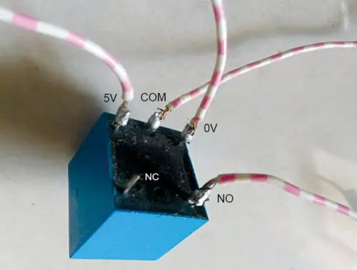
A 5V electromechanical relay (RL1) performs the actual switching of the light bulb on and off. As illustrated in Figure 4, this type of “sugar cube” relay has five terminals.
Two terminals are used to supply power to energize the coil inside the relay. The remaining three terminals serve different electrical contact functions:
Common (COM) provides a common connection point.
Normally Closed (NC) connects to COM when the relay is de-energized.
Normally Open (NO) is isolated from COM when de-energized.
In the circuit, the light bulb is connected between the NO and COM terminals. When the relay coil is not powered, the NO terminal is open. However, when the Arduino energizes the coil, the COM terminal temporarily bridges to NO, connecting the light bulb to the 230V AC mains supply and switching it on. This relay therefore allows the microcontroller to control AC power remotely.
In the AC power scheme, the Neutral (N) wire from the 230V source connects directly to the light bulb via the relay. Meanwhile, the Live (L) wire runs straight to the light bulb.
The Arduino’s operation is based on readings from the paired IR sensors. When Module2 (located outside) first detects motion followed by Module1 (inside) detecting the same, the microcontroller infers someone is entering. It then drives Pin 9 high to supply 5V.
However, this 5V output alone cannot energize the relay directly. So transistor T1 (a BC547 NPN amplifier) boosts the current to a level sufficient to power the relay coil. This closes the relay contacts, linking the Neutral wire to the light bulb and switching it on.
Conversely, if Module1 detects motion first followed by Module2, the Arduino realizes the person is exiting. It pulls Pin 9 low to remove the 5V, cutting off the transistor and de-energizing the relay. The light turns off as the Neutral wire is disconnected.
Both sensors are needed – using only one would not allow distinguishing entry from exit as the state would not change. Module2 is installed just outside the bathroom door, while Module1 remains near the inside of the door to reliably sense traffic.

Software
The Arduino Uno microcontroller serves as the brains to interpret signals from the two IR sensors and control the circuit accordingly. It runs software stored onboard in its internal memory.
Specifically, the software is written in the Arduino programming language and loaded using the Arduino IDE version 1.8.5. This IDE compiles and uploads the code, named “bathroom.ino”, to the microcontroller.
The ATmega328P chip on the Arduino features a pre-programmed bootloader that allows code upload without an external programmer. Within the code, a global variable called “count” is initialized to zero to track state.
The setup void contains initialization code wiring digital pins 7 and 8 as inputs for the sensors, and pin 9 as an output to control the relay. Serial communication is also initialized for debugging.
The core loop void handles the logic flow. It first checks the “in” sensor for a signal. Upon detection, a while loop executes to monitor the “out” sensor. Once that sensor also detects motion, the loop exits and count increments.
Conversely, if the “out” sensor detects first, count decrements in an else if block instead. For testing, a show function prints values over serial but is unnecessary in the final application. Together, the software enables automated control based on IR input readings.

The design assumes only a single person will occupy the bathroom at a given time. As such, the software monitors the “count” variable to determine the appropriate relay state.
As shown in Figure 5, an if statement checks if count equals one. This represents the scenario when a person has been detected entering but not yet exiting. If true, digital pin 9 is set high, energizing the relay and switching on the light.
Conversely, if count does not equal one, pin 9 is held low. This de-energizes the relay, disconnecting power to the light fixture.
By toggling pin 9 based solely on count equalling one, the circuit automatically accounts for someone being inside without requiring continuous sensing. This single-occupancy logic keeps the light on until detection of an exit, avoiding unnecessary switching from minor motion inside the bathroom area.
Construction and testing
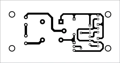
The circuit is constructed on a printed circuit board (PCB) with a layout depicted in Figures 6 and 7. As shown, the layout organizes the components and traces to efficiently route connections between pins.
Once the build is complete on the PCB, the “bathroom.ino” source code is uploaded to the Arduino Uno microcontroller. For testing and use, 5V DC power is applied at connector CON1 while 230V AC mains enter through CON2. The light fixture wires to connector CON3.
As illustrated in Figure 8, the paired infrared motion sensors are installed – one (Module 2) just outside the bathroom door, the other (Module 1) near the inside of the doorframe. This placement allows optimum detection of movement into and out of the room.
When powered up, connected to mains, and with the sensors installed as guided, the automated control system is ready for operation. It will now detect bathroom occupancy and automatically toggle the lighting accordingly without manual intervention.


- How does the system detect someone entering or exiting the washroom?
Two FC-51 IR sensor modules detect motion; the Arduino watches the order of low signals on the sensors to infer entry or exit. - Can the relay be driven directly from the Arduino pin 9?
No; the Arduino 5V output on pin 9 cannot directly energize the relay, so a BC547 transistor is used to boost current to the relay coil. - What happens when count equals one in the software?
If count equals one, the Arduino sets pin 9 high to energize the relay and turn the light on. - Which Arduino pins connect to the IR sensors?
IR Module1 Vout connects to digital pin 8 and IR Module2 Vout connects to digital pin 7 on the Arduino. - How is the light connected to the relay for mains switching?
The light is wired between the relay COM and NO terminals so energizing the relay closes COM to NO and connects the lamp to 230V AC. - Does the design support multiple people in the bathroom?
No; the design assumes only a single person occupies the bathroom at a time and uses count to track single occupancy. - What are the IR sensor module pin connections to the Arduino?
Each IR module has Vcc to Arduino 5V, GND to Arduino ground, and Vout to the designated digital input pin (7 or 8). - How is the software uploaded to the Arduino?
The bathroom.ino code is compiled and uploaded using Arduino IDE version 1.8.5 via the Arduino Uno bootloader.