
Summary of Smart Thermal + Arduino
This article describes a project using an Arduino and a temperature sensor to visualize liquid temperature via a gradient of LEDs. The system transitions from blue (cold) to red (hot), helping users determine if their coffee is at the right temperature without guessing.
Parts used in Smart Thermal + Arduino:
- 1 temperature sensor found in digital thermometers
- 9 colored LEDs: 1 red, 4 yellow, 3 green, 1 blue
- 1 resistor 10K (Brown, Black and Orange)
- 1 Arduino
- 1 thermal container
- Wires
Many times we are faced with a heat containing coffee and don’t know if the fluid is at the proper temperature and it is impossible to know just by looking at the bottle ended up losing time with a coffee that is cold and we get upset about it.
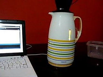
This however indicates maker by a graph LEDs if the liquid is hot, warm or cold. The LEDs gradually connect the blue (cold) to red (hot), when there is a heating and go off when there is a cooling.
Step 2: Sensor
The temperature sensor was removed from the tip of the digital thermometer and connected to the Arduino as shown below:
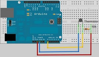
The sensor was placed inside the glass bottle with a long wire.
I developed a code that was based on another that controls the LED graphics that was modified and adapted to the needs of the project. In this program you can also see the serial port of the Arduino IDE value read by the sensor and the number of LEDs that are off.
Results:
It was possible to detect the gradual change in temperature of the fluid within the thermal result of cooling or heating the graph of LEDs.
To develop the project were used:
* 1 temperature sensor found in digital thermometers.
* 9 colored LEDs: 1 red, 4 yellow, 3verdes, 1 blue.
* 1 resistêcia 10K (Brown, Black and Orange).
* 1 Arduino.
* 1 thermal.
* wires.
Nine holes were drilled in the side of the thermal with a hot iron of the same diameter of the LEDs.
Wires connected the leds of the pins 5 ao 13
Internal view of wall of LED thermal:
For more detail: Smart Thermal + Arduino
- How does the device indicate liquid temperature?
The LEDs gradually connect from blue for cold to red for hot. - What happens to the LEDs when the liquid cools down?
The LEDs go off when there is cooling. - Where was the temperature sensor placed?
The sensor was placed inside the glass bottle with a long wire. - Which pins were the wires connected to for the LEDs?
Wires connected the LEDs from pins 5 to 13. - What colors make up the nine LED set?
The set includes 1 red, 4 yellow, 3 green, and 1 blue LED. - Can you see the serial port values in the code?
Yes, the program shows the serial port value read by the sensor and the number of LEDs that are off. - How were holes created for the LEDs?
Nine holes were drilled in the side of the thermal with a hot iron matching the LED diameter.
