After posting up the v1 of my project many people requested an more detailed instructable. So i decided to start with a new one with a little upgrades to my previous instructable.
What does this thing do?
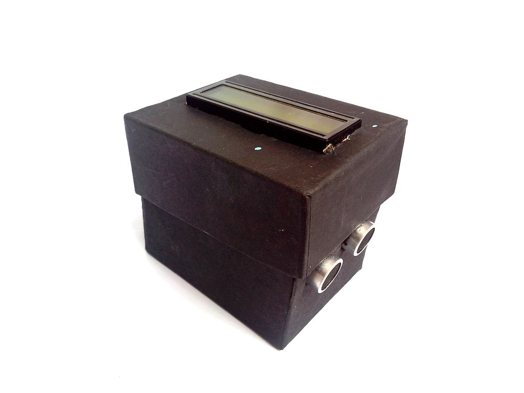
Well its quite simple it is just an replacement for an distance tape. It can also measure temperature, this was an upgrade to the old circuit. The measured distance is displayed on the LCD screen. And this circuit is powered with a 9V battery.
What upgrades have I done?
I created a beginners guide with more detail and an easier version of my previous instructable.
Why make this?
Well I need to do something this weekend……. And i wanted to be a part of makerlympics2014.
OK enough of the talking and lets start building…
Step 1: Tools and Components
Let’s start with gathering is all the parts. You may want to go step-wise or you will end up running all around when you start your build.
Components
- 1x Arduino Uno R3 (or similar board)
- 1x ultrasonic ranging module (HC-SR04)
- 1x Temperature sensor (lM35)
- 1x 16×2 LCD Display
- 1x 9V battery
- 1x PCB
- 1x 10k pot
Tools
- Soldering iron
- Multimeter
- A Laptop – mine is dell vostro 1540 (I know I’m old school)
Step 2: LCD-Arduino for beginners
I decided to change this to a beginners guide. So lets start with the basics of connecting the arduino to an LCD, if you think you know all of this you can proceed to the next step.
Materials required
- Arduino
- 10k Potentiometer
Procedure
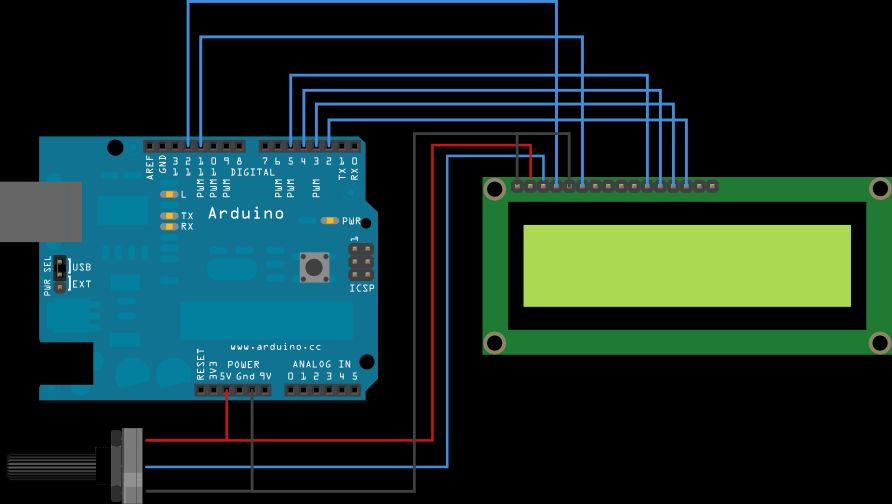
Lets start with connecting all the wires to the pins as shown in the circuit. If you want to use the backlight then, connect LCD pin 16 to GND and LCD pin 15 to +5V.
Use the pot to adjust the contrast of the LCD.
Open up your arduino IDE, then click File -> Examples -> LiquidCrystal -> HelloWorld. Upload the code to the board. You must now see “Hello World” on the lcd if all you see is black boxes then try adjusting the potentiometer.
If your done with all this proceed to the next step.
Step 3: LCD
Connect the LCD as per the circuit, I soldered the wires to a PCB and latter attached it to the arduino board.. pic for reference. The 10k variable resistance is used to adjust the contrast of the lcd display… If you are a beginner to arduino-LCD then you must read the previous step.
Here I used a black box I found in my house. On the lid of the box draw an outline of the LCD (mine was 17×2.4 cm),use a pair of scissors to cut through the box. Check if the LCD fits in, if it does you are good to go to the next step. If you want yours neat and tidy buy a box don’t follow my idea.
Extra Information
If your looking as to where to find the LCD then look for it on Ebay as there is a lot of 16×2 LCDs available over there.I have not given the LCD any back-light connection because I did not feel it was necessary.
Step 4: Ultrasonic module for beginners (HC-SR04)
Again this a guide for those who bought this module to build this project or for those who want to learn to connect the board. If you think you know how to set up the board you can skip this step.
Materials
- Arduino
- Ultrasonic distance module (HC-SR04)
- Breadboard
- Jumper wires
Procedure
The connections are relatively simple as compared to the LCD module all you have to connect is-
SR04 VCC pin to the Arduino 5v
SR04 GND pin to the Arduino GND
SR04 TRG pin to the Arduino Digital pin 12
SR04 ECHO pin to the Arduino Digital pin 11
Download the ping library from here, and place it in the arduino libraries folder. When you are done with that open up the Arduino IDE and you would fine an example code at this loacation File > Examples > NewPing > NewPingexample sketch. Upload the code to the board and Start the serial monitor you should get distance values in ‘cm’ on the screen. If you see this you can proceed to the next step.
Step 5: Ultrasonic distance module (HC-SR04)
For the ultrasonic range module I used HC-SR04 as it is easy to find and I had it available at my house from my previous robot. The module has a maximum distance of 4m. The readings are quite precise and it has its own library . You can find the library here. Read the previous step if you are trying this for the first time. The examples are include in the library.
Connect the module-
HC-SR04 VCC pin to the Arduino 5v
HC-SR04 GND pin to the Arduino GND
HC-SR04 TRG pin to the Arduino Digital pin
HC-12SR04 ECHO pin to the Arduino Digital pin 11
Draw the outline of the module and cut through the box with a pair of scissors. Try inserting the module and you can move to the next step
For more detail: Smart Distance Measuring Tape v2