
Summary of Simulate GPS/Read Photoresistor with MKR1000/ADAFRUIT
This article demonstrates an IoT project using an Arduino MKR1000 to read a photoresistor and simulate GPS data, publishing both to the Adafruit IO platform. The author explains how to set up feeds, connect via MQTT, and use simulated coordinates for testing before deploying real hardware. The code includes logic for analog reading, data formatting, and connection handling, providing a practical guide for beginners learning IoT development with Adafruit's ecosystem.
Parts used in the Simulate GPS/Read Photoresistor Project:
- Arduino MKR1000
- Photo resistor
- Resistor 1k ohm
- Arduino IDE
- ADAFRUIT IO
“ADAFRUIT IO” makes IoT for everyone. Here we publish the data from a photo-resistor and a simulated GPS.
Things used in this project
Hardware components |
||||||
 |
|
× | 1 | |||
 |
|
× | 1 | |||
 |
|
× | 1 | |||
Software apps and online services |
||||||
 |
|
|||||
|
||||||
Story
Introduction
How to face IoT, the best is trying and making by yourself with real hardware. In my case I began with MKR1000 – Arduino, the second challenge is to send the information to the web, in this case I find the platform from Adafruit.
With this context I decide to read a photo-resistor with the MKR1000 and publish the information with Adafruit IO. The idea is to learn by your self how to publish data with Adafruit IO, they have a lot a examples and here is also a way to learn.
The Adafruit IO has a GPS viewer and also a GPS and cellular hardware from FONA. Before buying such hardware it is a good idea to simulate the data interface. In this case I generate simulated coordinates but prepared according to the FONA 808 and sent in the right format to Adafruit, in order to have a feeling before to test with real hardware.
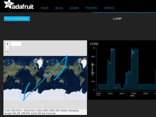
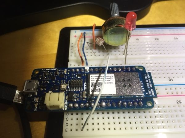
The serial monitor from the MKR1000 is showing information to control if all is running OK. Here are some screen shoots from the Adafruit GUI, the serial monitor information and the hardware.
Here is a link to the web, normally the hardware is running to test, if is not the case please write me down and I will assign you a time window to test and the the GUI interface.
https://io.adafruit.com/santanapablo1975/lamp-1
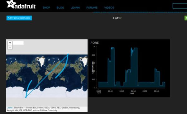
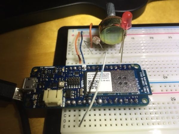
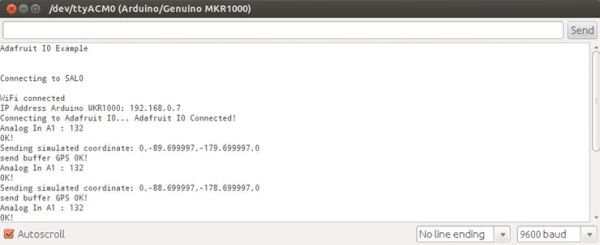
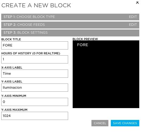
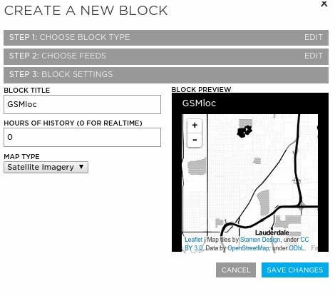
Here how to set up the blocks in ADAFRUIT:
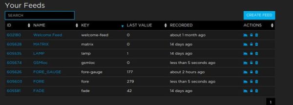
Here how the dashboard and feed look like in ADAFRUIT IoT:

Schematics
Code
Source : Simulate GPS/Read Photoresistor with MKR1000/ADAFRUIT
- How can I learn to publish data with Adafruit IO?
You can learn by trying and making projects yourself with real hardware like the MKR1000, as the platform provides many examples. - Can I simulate GPS data before buying real hardware?
Yes, it is recommended to generate simulated coordinates prepared according to the FONA 808 format to test the interface before purchasing hardware. - What hardware components are required for this project?
The project requires an Arduino MKR1000, a photo resistor, and a 1k ohm resistor. - Does the code handle WiFi connection errors?
Yes, the code includes a loop that retries the connection every 5 seconds if the status is not WL_CONNECTED. - What is the purpose of the serial monitor in this setup?
The serial monitor displays information to control if all processes are running OK and shows the analog input values and simulated coordinates. - How does the code simulate latitude and longitude changes?
The code uses incrementing variables (var and var_long) combined with a float value (var_1) to generate changing coordinate strings in a specific CSV format. - Which library is used to connect to the MQTT server?
The project uses the Adafruit MQTT Library along with the WiFi101 library for the MKR1000. - What happens if the MQTT connection fails during the loop?
The code attempts to ping the server; if the ping fails or the client is not connected, it calls the connect function to reconnect.
