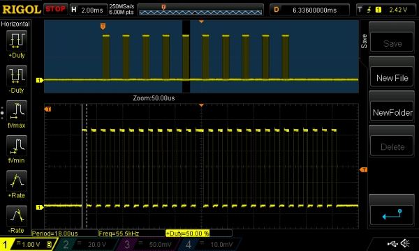
We are often asked on discussion boards, about conflicts between IRremote or IRLib and other Arduino Libraries. In this post, we present a sketch for ‘Simple Infrared PWM on Arduino’. This is the first part in a 3 part series of posts. Part 1 shows how to generate the simple Infrared carrier frequency on Arduino, using any available IO pin and without conflicting with other libraries. Part 2 will show how to send a RAW infrared signal using this approach and Part 3 will show how to send a common NEC signal from the binary or HEX value.
Definitions
#define Duty_Cycle 56  //in percent (10->50), usually 33 or 50
//TIP for true 50% use a value of 56, because of rounding errors
//TIP for true 40% use a value of 48, because of rounding errors
//TIP for true 33% use a value of 40, because of rounding errors

#define Carrier_Frequency 56000   //usually one of 38000, 40000, 36000, 56000, 33000, 30000

#define PERIOD    (1000000+Carrier_Frequency/2)/Carrier_Frequency
#define HIGHTIME  PERIOD*Duty_Cycle/100
#define LOWTIME   PERIOD - HIGHTIME
#define txPinIR   8   //IR carrier output
 First we configure the duty cycle for the Infrared carrier. Typically, values of 33% or 50% are used for IR, with 33% being popular in battery-powered systems. You will note our suggestions to use a value of 56 for 50% duty cycle and 40 for 33%, which is an artefact of rounding errors in the ‘#define’ statements. In simple terms set Duty_Cycle to 56 for a 50% duty cycle. Next we define the carrier frequency. Almost all IR systems us a carrier frequency of either 38kHz, 40kHz, 36kHz, 56kHz, 33kHz or 30kHz. In addition, Bang & Olufsen systems use a carrier frequency of 455kHz. However, this is very rare in use and is outside the scope of this sketch. The PERIOD is a simple calculation based on the defined carrier frequency. Similarly, HIGHTIME and LOWTIME are calculated automatically based on the period and the duty cycle. AS we mentioned before, you can select any Arduino pin for the IR output signal, including all digital and analogue pins.
Setup
void setup() {
/*
  Serial.begin(9600); //debug info
  while(!Serial);
  delay(500);
  Serial.println(PERIOD);
  Serial.println(HIGHTIME);
  Serial.println(LOWTIME);
*/

  pinMode(txPinIR,OUTPUT);
}
As you can see from the setup function above, you only need to set the txPinIR to OUTPUT. The other code is purely for debugging to see the calculated values and can be uncommented as you wish.
Loop
void loop() {
 for (int i=0;i<10;i++){
   mark(500);
   space(1000);
 }
 delay(5000);
}
For part 1, we demonstrate how to generate a basic Infrared signal using a for loop, mark, space and delay functions. This generates a signal every 5 seconds approximately. The signal consists of 10 pairs of mark and spaces. The marks are 500 microseconds long and the spaces are 1000 microseconds long (or 1 ms). In the following parts in this series we will see how to generate real world examples of Infrared signals. You can see an oscilloscope image of this signal above.
Mark
void mark(unsigned long mLen) {
  if (mLen==0) return;
  unsigned long now = micros();
  while ((micros() - now) < mLen) {
    digitalWrite(txPinIR, HIGH);
    delayMicroseconds(HIGHTIME-6);
    digitalWrite(txPinIR, LOW);
    delayMicroseconds(LOWTIME-7);
  }
}
(At this point we suggest that you check out an excellent site that explains the structure of IR signals, if you are not familiar with the concept of marks and spaces.) The code in the mark function shown above simply toggles the txPinIR high and low very rapidly to create the carrier at the configured frequency and duty cycle. You will also notice the adjustments made (-6 & -7) which are required because of the overhead in this code. In particular, digitalWrite is very (relatively) slow. An interesting feature of this mark function is that it can handle very long duration marks, unlike IRremote.
For more detail: Simple Infrared PWM on Arduino
