
Summary of A simple DIY spectrophotometer using raduino
This article guides readers through building a functional, basic DIY spectrophotometer using accessible components. The project demonstrates the fundamental principles of measuring light absorbance by splitting light into a spectrum via a diffraction grating (or CD), selecting specific wavelengths with a slit, and detecting the intensity after it passes through a sample. While not comparable to commercial equipment, it serves as an educational tool for understanding spectrometry.
Parts used in the DIY Spectrophotometer:
- Stepper motor
- Arduino board or stepper driver circuit
- L293D H-Bridge
- NPN transistors (BC547A)
- Resistors (10k, 1k, 2k2, 4k7)
- Op-amp (TL081)
- LDR (Light Dependent Resistor)
- LED and Lightbulb
- Diffraction grating or CD/DVD
- Cuvette
- Base board (e.g., cutting board)
- Metal or cardboard plaques
- Connectors and pushbuttons
- Power supply
What’s all this?
This instructable will explain how to build a fairly basic but working spectrophotometer out of easily sourceable parts.
Of course, this device is nothing compared to a commercial spectrophotometer, but it will allow the builder to understand how such a device works.
Huh? What are you talking about?!
A spectrophotometer measures the amount of light that a certain sample absorbs.
The basic principle:
- A beam of light passes through a prism or diffraction grating.
- Out of the resulting spectrum, a certain (range of) wavelength(s) gets selected by sending the light through a slit.
- The light passes through the sample and hits a detector.
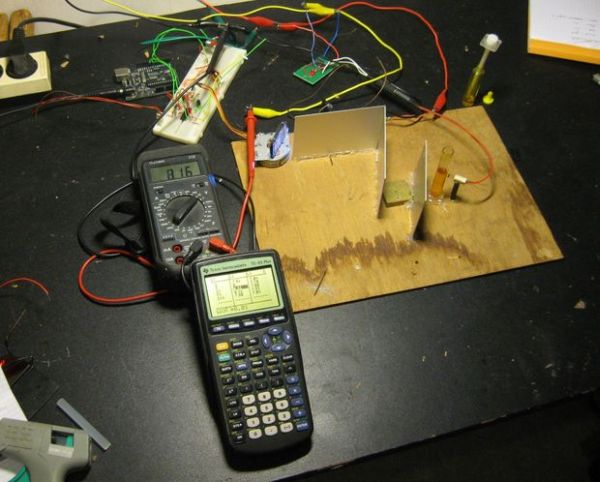
This way, one can build a “spectrometric fingerprint” of a certain sample that will depend on the molecules in the sample.
Cool, let’s do it!
I’d once again like to emphasize that this device is certainly not to be compared to a commercial system, but if you’re looking for a fun project that will enable you to learn something more about the workings of a spectrophotometer, this project is for you!
Step 1: Sourcing the parts
Most parts are fairly easy to obtain.
You will need:
For the stepper circuit:
- A stepper motor
- an Arduino (or a stepper driver circuit)
- 2x 10k resistor
- 2x 1k resistor
- L293D H-Bridge
- 2x NPN transistor (I used the BC547A)
- A power supply
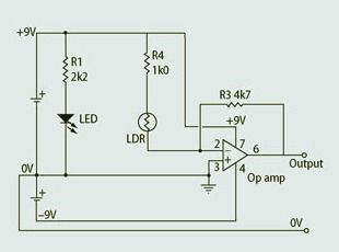
For the detection and amplification circuit:
- an op-amp (e.g. TL081)
- LDR
- 1x 2k2 resistor
- 1x 4k7 resistor
- 1x LED
General parts
- A base (some kind of board such as a cutting board to mount everything on)
- Cuvette
- Diffraction grating, CD or DVD
- Lightbulb and / or white LED
- Metal or cardboard plaques
- Some connectors
- Some pushbuttons
Step 2: Bring on the photons!
Light source
First of all, we need a light source. Some possibilities include a small lightbulb or white LED. I installed both, so I could experimentally decide which one was best suited for my purposes.
To construct the light source assembly, find some piece of plastic (or any other material, for that matter) and glue a bulb socket to it.
For the LED, find some kind of connector (I cut off part of and old IDE-connector) and solder some wires to it. Also include a 2k2 resistor in series with the LED to limit the current.
Glue the LED-connector somewhere near the bulb, and put in a LED.
Step 3: Diffraction
Splitting the light
To be able to select a certain wavelength (the color of light depends on its wavelength) we first need to split the light into a spectrum.
This can be accomplished by a diffraction grating. Since most people don’t have diffraction gratings lying around the house, a CD can be used as well.
Take a look here for some background information.
Note that a CD does not exactly produce an even spectrum, so it’ll give nowhere near as accurate results as with a “real” diffraction grating.
Selecting the wavelength
Since we want to measure the absorbance of the sample at a certain wavelength (or in this case, range of wavelengths) we need to be able to select a certain part of the spectrum.
This can be accomplished with a “slit”, i.e. a sheet of cardboard or metal with a narrow slit in it.
To choose which part of the spectrum passes through the slit we can vary the angle with which the light hits the CD.
I chose to use a stepper motor because it can be turned in discrete steps.
Driving the stepper
The stepper motor can easily be driven with an Arduino board. Construct the bipolar stepper driving circuit found here and use the included Arduino-code “spectrostepper.pde”, the motor can be controlled by two pushbuttons.
Construct the driver circuit. Then, add pushbuttons by connecting one leg of a 2k2 resistor (pull-down resistor) to ground, connect the other leg to one leg of the pushbutton AND to a digital input on the Arduino.
Then, connect the other leg of the pushbutton to +5V from the Arduino.
Connect the motor itself to a power source, load the sketch in the Arduino and drive the stepper!
If everything went right, the motor should turn 1 step when you push a button; direction depending on which button you press.
Bringing it together
Once you got the stepper going, connect the CD to the motor. (I, once again, used hot glue)
For more detail: A simple DIY spectrophotometer
-
What is the main purpose of this project?
To build a working device that allows the builder to understand how a spectrophotometer works by measuring light absorbance. -
How does the device select a specific wavelength?
It uses a slit to select a part of the spectrum created by a diffraction grating, varying the angle at which light hits the grating. -
Can a CD be used instead of a diffraction grating?
Yes, a CD can be used as a diffraction grating, though it produces an uneven spectrum and yields less accurate results than a real one. -
What component is used to drive the mechanism for changing angles?
A stepper motor is used because it can be turned in discrete steps to adjust the angle of the light source. -
How is the stepper motor controlled in this build?
The motor is driven by an Arduino board using a specific sketch and controlled by two pushbuttons to move forward or backward. -
What parts are needed for the detection circuit?
The detection circuit requires an op-amp (like TL081), an LDR, a 2k2 resistor, a 4k7 resistor, and an LED. -
How should the LED be connected in the light source assembly?
A 2k2 resistor must be included in series with the LED to limit the current. -
What is the role of the cuvette in this project?
The cuvette holds the sample through which the selected light passes before hitting the detector.
