Summary of A simple DIY Oscilloscope with Arduino Uno and Mega
Summary (under 100 words): I built a simple DIY oscilloscope using Arduino Uno/Mega and a 2.4 inch TFT display to visualize RF and IR signals. After trying many outdated tutorials, I adapted working code from a Japanese oscilloscope project and a TFT library to display two channels, frequency, waveform type, and approximate amplitude within a 0–5V input range. The project includes screenshots, video, and links to the combined code and original sources.
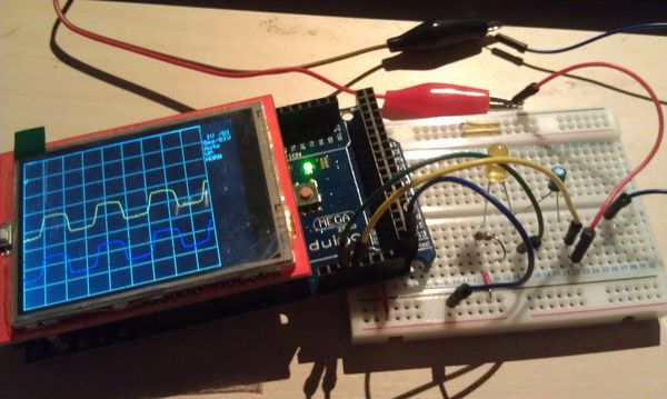
Parts used in the My DIY Oscilloscope:
- Arduino Uno or Arduino Mega
- 2.4 inch TFT touchscreen shield
- Signal sources (RF and IR receivers used for testing)
- Connecting wires/jumper cables
- USB cable for Arduino and programming
- Computer with Arduino IDE
My DIY Oscilloscope, how i got my signal
Content :
– Description
– Screenshots
– Video
– Credits and links
Descriptions
I am experimenting with RF and IR signals in various frequencies and had some trouble with the receivers and needed to see what kind of signal i was receiving.
I cannot afford a real oscilloscope but i knew about the older Arduino oscilloscopes.
After trying many different versions of code and tutorials, I was unable to get a single one to work, and all the tutorials and guides around was 2-3 years old.
Not sure if it is the IDE or the actual hardware that has changed in such a way that it didn’t work anymore.
I finally found a working oscilloscope from a Japanese website, (linked below) and a working TFT screen library,
meaning i could read the various signals received.
Clearly the limitations are 0-5v but that is fine, what i needed to know is either wave type and frequency, and this is sufficient.
It also gives me an indication of the amplitude which is just a nice bonus.
But what I’m most happy with, is the two channel feature, i often use the second channel as a reference point to be able to
differentiate the main channel on the screen.
Credits and Links :
My compilation of the Oscilloscope and TFT library ( what you see on the video and images ) :
https://dl.dropboxusercontent.com/u/19761809/arduino/Vaupell-Oscilloscope.zip
Original Oscilloscope link (code by : Noriaki Mitsunaga ) :
http://n.mtng.org/ele/arduino/oscillo-j.html
Original TFT display link ( TFT shield library source ) :
http://www.smokeandwires.co.nz/blog/a-2-4-tft-touchscreen-shield-for-arduino/
TFT library :
Library : https://github.com/Smoke-And-Wires/TFT-Shield-Example-Code
Source: A simple DIY Oscilloscope with Arduino Uno and Mega
- What microcontrollers are used in this DIY oscilloscope?
The project uses Arduino Uno and Arduino Mega as the microcontrollers. - Can this oscilloscope display two channels?
Yes, the implementation supports two channels and the second channel is often used as a reference. - What voltage range can this DIY oscilloscope handle?
The oscilloscope is limited to 0–5V input range. - How was working code obtained for this project?
Working oscilloscope code was found on a Japanese website and combined with a TFT screen library. - Which TFT library is used for the display?
The TFT Shield Example Code library from Smoke-And-Wires on GitHub is used. - Where can I find the compiled oscilloscope and TFT library used here?
The author provided a compiled package available via a Dropbox link in the credits. - Does this DIY oscilloscope show amplitude information?
Yes, it provides an indication of amplitude as an additional feature. - Why were older tutorials not useful?
Many tutorials were 2–3 years old and did not work with updated IDE or hardware changes, prompting the author to find newer working code.