
Summary of How to Set Up and Program an LCD Display on an Arduino
Summary: This tutorial explains wiring and programming a 16×2 LCD with an Arduino using the HD44780-compatible driver in 4-bit mode. It covers printing, scrolling, positioning, blinking, and creating custom characters, includes wiring diagrams, notes on a 220 Ω backlight resistor, and offers a downloadable quick start guide with code and diagrams.
Parts used in the 16×2 LCD Arduino Tutorial:
- 16×2 LCD display (HD44780 compatible)
- Arduino (any compatible board)
- Breadboard
- Jumper wires
- 16-pin header (may need soldering)
- 220 Ohm resistor (for backlight)
- Potentiometer for contrast (commonly used with LCDs)
- Power supply or USB cable for Arduino
In this tutorial, I’ll explain how to set up an LCD on an Arduino and show you all the different ways you can program it. I’ll show you how to print text, scroll text, make custom characters, blink text, and position text. They’re great for any project that outputs data, and they can make your project a lot more interesting and interactive.
The display I’m using is a 16×2 LCD display that I bought for about $5. You may be wondering why it’s called a 16×2 LCD. The part 16×2 means that the LCD has 2 lines, and can display 16 characters per line. Therefore, a 16×2 LCD screen can display up to 32 characters at once. It is possible to display more than 32 characters with scrolling though.
The code in this article is written for LCD’s that use the standard Hitachi HD44780 driver. If your LCD has 16 pins, then it probably has the Hitachi HD44780 driver. These displays can be wired in either 4 bit mode or 8 bit mode. Wiring the LCD in 4 bit mode is usually preferred since it uses four less wires than 8 bit mode. In practice, there isn’t a noticeable difference in performance between the two modes. In this tutorial, I’ll connect the LCD in 4 bit mode.
Connecting the LCD to the Arduino
Here’s a diagram of the pins on the LCD I’m using. The connections from each pin to the Arduino will be the same, but your pins might be arranged differently on the LCD. Be sure to check the datasheet or look for labels on your particular LCD:
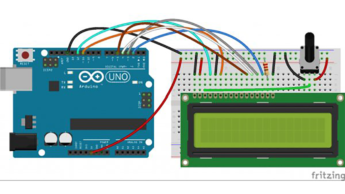
Also, you might need to solder a 16 pin header to your LCD before connecting it to a breadboard. Follow the diagram below to wire the LCD to your Arduino:
The resistor in the diagram above sets the backlight brightness. A typical value is 220 Ohms, but other values will work too. Smaller resistors will make the backlight brighter.
Read more: How to Set Up and Program an LCD Display on an Arduino
- Why is it called a 16×2 LCD?
Because it has 2 lines and can display 16 characters per line, totaling 32 characters at once. - What driver does the tutorial code target?
The code is written for LCDs that use the standard Hitachi HD44780 driver. - How many pins indicate the LCD likely uses the HD44780 driver?
If your LCD has 16 pins, then it probably has the Hitachi HD44780 driver. - Should I wire the LCD in 4 bit or 8 bit mode?
The tutorial connects the LCD in 4 bit mode, which is preferred because it uses four fewer wires. - Is there a performance difference between 4 bit and 8 bit modes?
In practice, there isn’t a noticeable difference in performance between the two modes. - What does the resistor in the wiring diagram do?
The resistor sets the backlight brightness. - What value resistor is typical for the backlight?
A typical value is 220 Ohms, though other values will work. - Will a smaller resistor affect backlight brightness?
Yes, smaller resistors will make the backlight brighter. - Do I need to solder a header to the LCD?
You might need to solder a 16 pin header to your LCD before connecting it to a breadboard. - Is there a quick start guide available?
Yes, the author provides a downloadable quick start guide covering steps, diagrams, and code.
