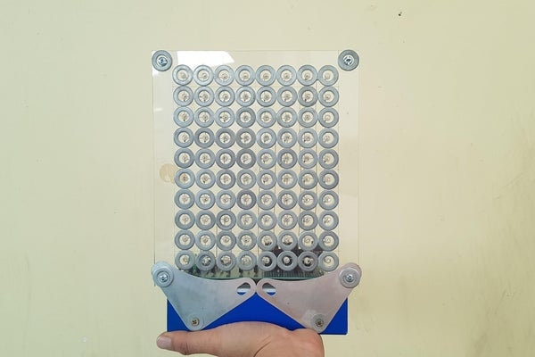
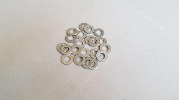
I do project related works. After the structure contractors finished their building works, they threw away a lot of washers and nuts M10. During I did cleaning, I picked them up to make this decorative see-through led project. It can be viewed from frontside or backside by a push button.
Let’s watch videos bellow before getting started.
- Scrolling text, view from frontside.
Internet clock, view from backside. It looks even better.
Step 1: Things We Need
Main component are as below:
- 100pcs x LED 5mm, red color in my case.
- 1pcs x Wemos D1 R2.
- 1pcs x 4-to-16 Decoder/Demux CD74HC154E (or 2pcs x 74HC138 – 3 to 8 Line Decoder).
- 1pcs x Power Logic 8-Bit Shift Register TPIC6B595N.
- 10pcs x Transistor A1013.
- 8pcs x R100.
- 10pcs x R1K.
- 1pcs x Capacitor 0.1uF.
- 1pcs x Double Side DIY Proto-board Circuit 9x15cm.
- 1pcs x Female 40pin 2.54mm Header.
- 1pcs x Male 40pin 2.54mm Header.
- 4pcs x Copper/ Plastic Standoff Spacers 5mm.
- 1pcs x Steel junction box W x L x H = 115 x 175 x 40mm.
- 100pcs x Washers for bolt M10.
- 1pcs x Clear Acrylic Plate A4 size, thickness 5mm.
- 1pcs x White Acrylic Plate A4 size, thickness 3mm.
- 1pcs x Power Supply 5V, minimum 2A.
- 1 meter x Solid copper conductor 1 ~ 1.5 mm.
- 1meter x 8P Rainbow Ribbon Cable.
- Some bolts, nuts, washer M4.
Tools:
- Hot glue gun.
- Drilling machine with 5mm drill bit.
- One wooden plate A4 size, thickness 10mm.
- Soldering machine.
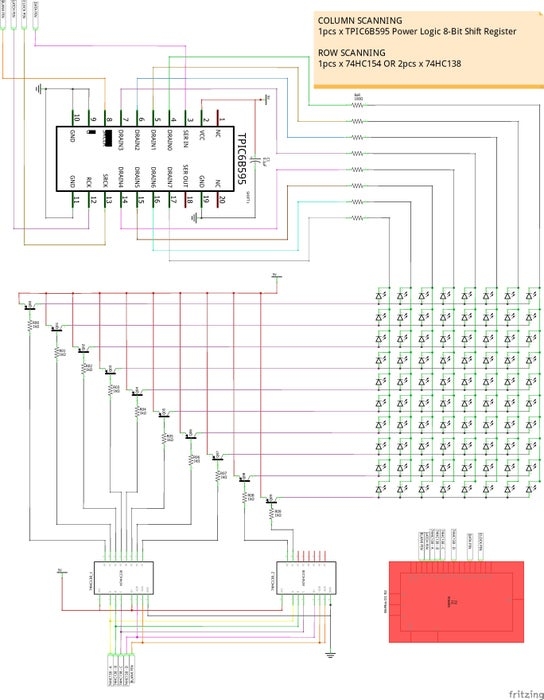
Step 2: Schematic
You can download schematic with high resolution PDF file HERE.
For scanning ten led rows, we can use 1pcs x CD74HC154E – 4 to 16 Line Decoder or 2pcs x 74HC138 – 3 to 8 Line Decoder. In my case, I used 1pcs x CD74HC154E.
My see-through led matrix 8×10 consists of:
- Ten led rows (anodes) are connected to the CD74HC154E + NPN Transistors A1013 through resistors 1K.
- Eight led columns (cathodes) are connected to the TPIC6B595N Power Logic 8-Bit Shift Register + R100 current limiting resistors.
Step 3: Assembly Works
- Selecting 80 washers for M10 bolts that weren’t rusted and had a nice shape. The washers I used for this project have an outer diameter 20mm, and inner diameter 10mm.
- Cutting a clear acrylic plate in 200 x 230mm size.
- Using hot glue to stick the 80 washers onto the clear acrylic sheet carefully. Because the washers are in contact each other so the distance between their centers are also 20mm in horizontally or vertically. In addition, I stuck 4 more washers at four acrylic sheet corners.
- Marking the center of each washers then drilled with a 5mm drill bit at all the marked points.
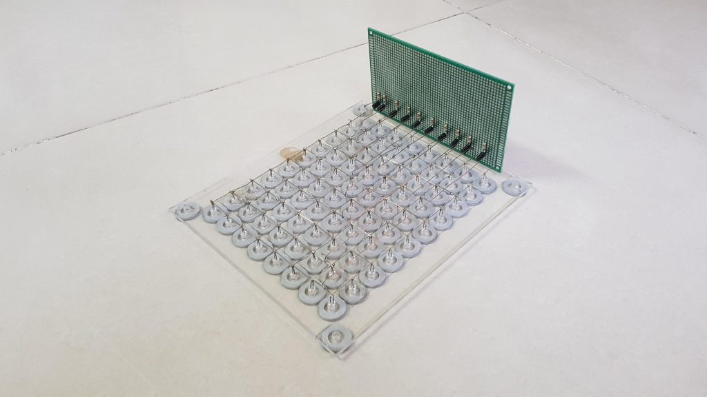
- We can use this acrylic plate to make a led matrix soldering template but it can be scorched when the hot solder lead falls on. So I used a wooden template with the same led spacing 20mm. It only has 64 holes corresponding to 8 rows and 8 columns but it is okay, the remaining 2 led rows could be soldered on the acrylic plate.
- Soldering led matrix.
- Finish the 8×8 led matrix.
- Inserting an 8×8 matrix leds into the holes on acrylic plate and soldered the remaining 2 rows. The 8×10 led matrix was completed.
Step 4: Electrical Connection Works
All components were soldered following to the schematic diagram in STEP 2. I did this circuit by handmade, and arranged all ICs on top side of PCB, all wires are hidden underneath the PCB.
- Soldering 10 led rows (anodes) by copper wires to PCB 9x15cm at transistor A1013 output pins and 8 led columns (cathodes) were also soldered to PCB by led pins. Resistors 1K and 100 ohm were also soldered afterwards.
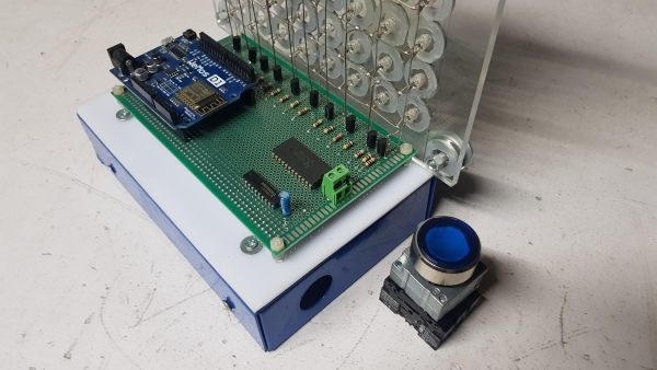
- All remaining components were soldered on the PCB including Wemos female headers. We can see the top view of PCB
- And here below is bottom view
- Soldering male headers to Wemos R1 D2 at available spare holes on the board.
- Plugging Wemos onto the DIY PCB.
- Connecting the leds and control PCB to the box. I used 2 nice supports to keep the acrylic sheet firmly connected to the box. The box is made of steel so it is heavy enough to hold the led and acrylic plate from falling off.
- All components are exposed when we look from backside.
Step 5: Programming
The Arduino code for this project is available at my GitHub.
Note: To switch from frontside to backside view, I used one industrial push button and installed it into the box’s hole, diameter 21mm.
Source: SEE-THROUGH LED MATRIX WITH WASHERS