
Summary of ScopeFun – Open Source All-in-One Instrumentation
ScopeFun is an open-source, all-in-one benchtop instrument combining an oscilloscope, arbitrary waveform generator, spectrum analyzer, logic analyzer, and digital pattern generator. Its hardware centers on a Xilinx Artix-7 FPGA with 512 MB DDR3 SDRAM for buffering. It features USB 3.1 Gen1 connectivity via Cypress FX3, drawing power directly from the USB port. The device offers two analog channels for oscilloscope inputs with 250 Msps sampling (up to 500 Msps interleaved) and supports Equivalent Time Sampling at 2 GSps. Additionally, it includes two waveform generator outputs capable of producing up to 4 Vpp at 200 Msps per channel using CORDIC algorithms and custom data uploads.
Parts used in ScopeFun:
- Xilinx Artix-7 FPGA
- 512 MB DDR3 SDRAM
- Cypress FX3 USB 3.1 Gen1 chip
- Analog front end for impedance, level, and offset adjustments
- Two 10-bit analog-to-digital converters (ADCs)
- FPGA LUT delay line for trigger logic
- Dual digital-to-analog converters (DACs)
- Internal FPGA BRAM for custom waveform storage
- CORDIC algorithm module for sine wave generation
Five Benchtop Tools in One Open Source Device.
ScopeFun in an open source, all-in-one instrumentation platform. It includes an oscilloscope, arbitrary waveform generator, spectrum analyzer, logic analyzer, and digital pattern generator.
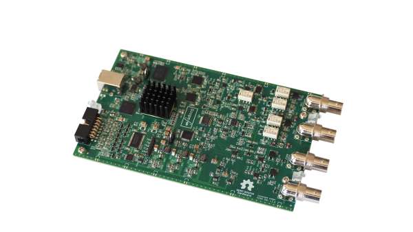
Hardware
Hardware is built around Xilinx Artix-7 FPGA with an onboard RAM available for buffering samples (512 MB DDR3 SDRAM). All hardware settings are controlled via software GUI. USB connectivity is provided via Cypress’s FX3 USB 3.1 Gen1 chip. Hardware is USB powered which eliminates the need for additional power supply. Below you can find more information about individual hardware components.
Oscilloscope
Two analog channels are available as oscilloscope inputs. Both oscilloscope channels are protected against overvoltages up to +/- 50 V. Input coupling selection is available (DC, AC, GND) and is controlled via program GUI. Input signals are buffered via analog front end for impedance, level (gain) and offset adjustments. Each analog channel is sampled at 250 Msps with 10-bit analog-to-digital converter (ADC). Two ADC’s can be configured for sampling in interleaved mode which provides a single channel sampling speed of 500 Msps. Digital samples are processed by FPGA which also contains trigger logic. When trigger condition is met, samples are transferred to onboard DDR3 SDRAM which provides buffer length of 128 Mega samples per channel. Hardware also supports Equivalent Time Sampling (ETS). For this purpose an analog trigger signal is sampled inside FPGA LUT delay line to determine exact time of trigger event relative to the ADC sampling clock. This provides a sampling speed of 2 GSps for repetitive signals.
Waveform Generator
There are two generator outputs with which can generate voltages up to 4 Vpp. Both AWG channels are protected against short circuit and overvoltage (+/- 25 V). Generator channels have 50 Ohm output impedance which allows connection to various equipment. User can select waveform shape, frequency, level and offset via program GUI and settings are immediately reflected in FPGA control registers. Digital samples are generated inside FPGA at 200 Msps per channel and transferred to dual digital-to-analog converter (DAC). Simple signals are derived from counters. Sine wave output is generated with the help of CORDIC algorithm, so that outputs of arbitrary frequency can be obtained. User can also provide a custom waveform sample data and upload it to FPGA internal memory (BRAM).
Read more: ScopeFun – Open Source All-in-One Instrumentation
-
What functions does ScopeFun combine into one device?
It combines an oscilloscope, arbitrary waveform generator, spectrum analyzer, logic analyzer, and digital pattern generator. -
How is the hardware powered?
The hardware is USB powered, which eliminates the need for an additional power supply. -
What is the maximum sampling speed for repetitive signals?
Equivalent Time Sampling provides a sampling speed of 2 GSps for repetitive signals. -
Can users upload custom waveform data?
Yes, users can provide custom waveform sample data and upload it to the FPGA internal memory known as BRAM. -
What algorithm is used to generate sine wave outputs?
Sine wave output is generated with the help of the CORDIC algorithm. -
How many analog channels are available for oscilloscope inputs?
There are two analog channels available as oscilloscope inputs. -
What is the voltage protection limit for the oscilloscope inputs?
Both oscilloscope channels are protected against overvoltages up to plus or minus 50 V. -
What is the maximum output voltage for the waveform generators?
The two generator outputs can generate voltages up to 4 Vpp.
