This instructable was created in fulfillment of the project requirement of the Makecourse at the University of South Florida (www.makecourse.com).
What is an DIY project? DIY also known as Do It Yourself, is often denoted as projects that can be completed by oneself rather than employing a professional. That is what most engineers in their own respective fields do. They either are creating or building exciting new projects that can change the future. But are you a engineer if all you do is run simulations and calculating numbers on their computer screen? The answer is no, you are not an engineer until you have dive into the world of creating and building. So follow me on this journey of learning and building to become a true engineer. The Rocket Launch Pad is an exciting project that allows students to learn more about Arduino, programming, laser cutting, 3D printing, and creating their own rocket fuel.
Step 1: Parts Needed for Rocket System
To start it off, we will need parts for the electronic portion of the rocket system. Below is a list of wires, electronic components, and other parts needed:
- 1 x 1/4″ Dowel wood
- 1 x 3/4″ Dowel wood
- 1 x 3/4″ Schedule 40 PVC pipe
- 1 x Bag of Potassium Nitrate
- 1 x Bag of Powder Sugar
- 1 x Blender
- 1 x Cat Litter, but make sure it is the bentonite clay kind
- 4 x Rubberbands
- 1 x Arduino Microcontroller Board
- 1 x Breadboard
- 2 x 28BYJ-48 stepper motors
- 2 x ULN2003 motorboards
- 1 x 3-6V DC motor
- 1 x IR sensor
- 1 x IR remote
- 1 x 220 Ohm resistor
- 2 x 2N2222 NPN Transistors
- 1 x Diode
- 3 x 9V batteries
- 1 x 6 pack of Estes Igniters
- 1 x Box of Matches
- Lots of jumper wires
- Lots of male to female wires
Step 2: Design the Box
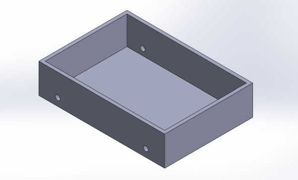
The first step to create the launch pad is by designing. First design the box that will fit all the electronic components. The size is up to you to decide, but make sure there is enough room for everything. The dimensions I used for my box is 10″ x 7″ with a height of 2.35″. The wall thickness is 1/4″. With a moving platform you will need wheels for the box to move. Make sure to create 4 holes with the dimensions of 0.38″, and again this dimension is chosen because the type of stepper motor that I used.
Step 3: The Cover
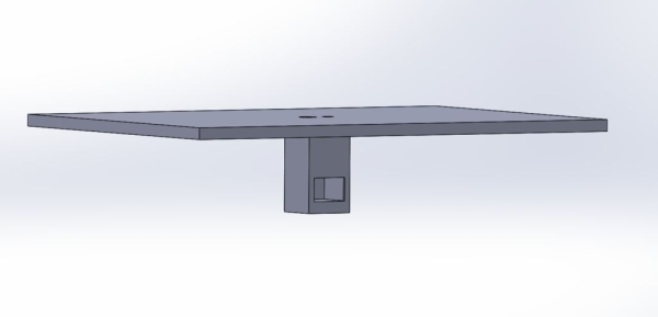
Next, design the cover that will act as the launch platform for the rocket. The dimension that I used is 10″ x 7″, with a height of 1/4″. At the center create two holes one is for the rotational portion of the rocket and the other is for the igniter that will sit under the rocket. The dimensions are 0.45″ for the igniter hole and 0.25″ for the rotational hole. Under the cover create a housing that will hold the DC motor that will be used for rotating the rocket. The dimensions are 1″ x 1″ x 1.75″. Also create a cut out on whatever side you want, this is to allow wiring under the housing for the DC motor and igniter.
Step 4: The Rocket
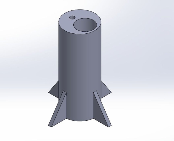
Design the rocket however you want, but the rocket will need to have a 0.25″ hole for the dowel wood that will be used a rotation. Also a hole with a diameter of 1.1″ and 5″ deep. You can look up the outer diameter size for a schedule 40 PVC with a 3/4″ Nominal Pipe Size.
Step 5: The Wheel
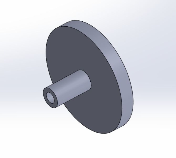
Lastly, we need wheels to move the rocket platform. The wheel needs to have a diameter of 2″ and a thickness of 0.25″. The shaft that will be rotating needs to be 0.38″ in diameter with a length of 0.75″. The inner diameter of the shaft needs to be whatever dimension that is needed for whatever kind of motor you use. For an example, the stepper motor that I am using is the 28byj-48 stepper motor and the inner diameter of the shaft that is needed to fit this motor is 0.205″.
Step 6: Box Assembly
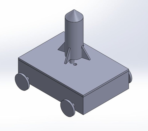
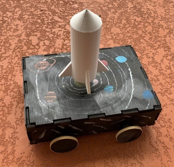
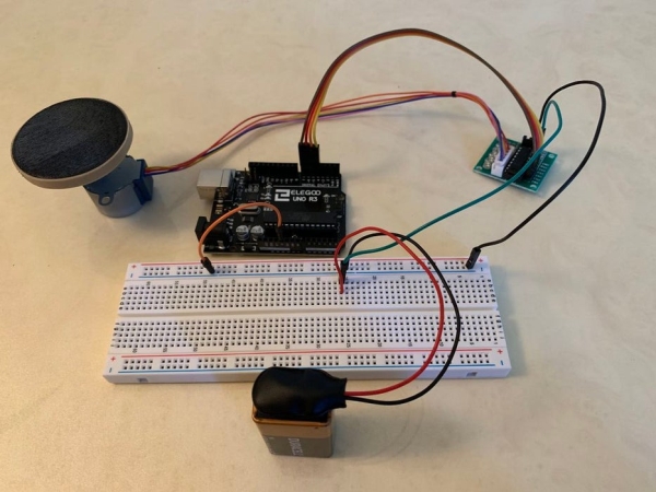
You can use wood or any material that you want to create the box. From 3D printing to laser cutting wood, it is totally up to you. Just make sure you convert the files from Solidworks to DXF for laser cutting and into STL for 3D printing. When you put together the box it should look something like the picture presented. Now set the box aside and now lets focus on the electronic components needed for the project.
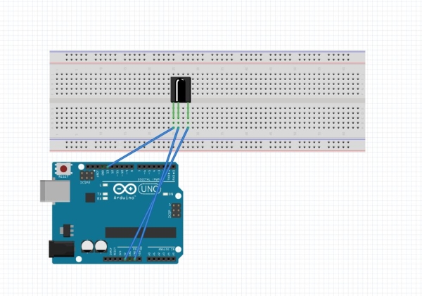
Step 7: Setting Up the IR Sensor

The first electronic component that needs to be setup is the IR sensor. Use jumper wires to create a circuit between the arduino and breadboard. Connect the 5V pin from the arduino on the breadboard as well as the ground pin to the breadboard. Connect pin 13 from the arduino to the IR sensor.
Step 8: Setting Up DC Motor
Next we need to setup the DC motor. Place a NPN transistor onto the breadboard, anywhere is fine, use jumper wires to connect the ground between the arduino and the transistor. Then place a resistor in the center of the transistor and connect the end of the resistor to pin 3 on your arduino. Next, place a diode on the last leg of the transistor and connect the end of the diode to the 5V pin on the arduino. Lastly place the DC motor’s positive leg where the diode and 5V meet, place the negative leg where the diode leg and transistor leg meet.
Step 9: Setting Up the Igniter Circuit
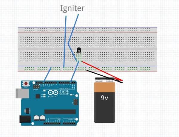
The igniter setup is similar to the DC motor setup. You will need a NPN transistor, place that transistor anywhere on the breadboard. Connect ground between the arduino and breadboard, this should be the first thing you do always. Next connect the positive end of the 9V battery to the right leg of the transistor, this is the collector leg, and connect the negative end to ground. On the other side which is the emitter end, connect the positive leg of the igniter to the emitter end and connect the negative leg of the igniter to ground. This setup will create a relay, so when you press a button from your remote control it will close the circuit and grab the voltage from the 9V battery.
Step 10: Connecting the Two Stepper Motors
Lastly connecting the stepper motors, since there are two of these you will have to do this twice. Connect the pins from the stepper motor to the ULN2003 motor board. On the motor board there will be 4 pins lined up on it’s side from IN1 – IN4, connect those to the arduino in order. For an example, if its IN1 connect that to pin 4, the last pin should be IN4 and that is connected to pin 7. Next, wire a external 9V battery to the breadboard, you will need this because the motors cannot be run off on the arduino. Connect the positive power on the motor board to the 9V battery positive lead and do the same for the negative.
Step 11: The Functionality of Your System
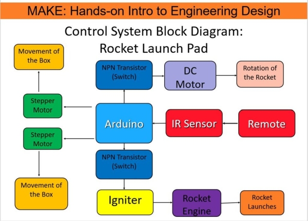
The picture above shows the control diagram of your system. The IR sensor needs to receive a signal from the remote, once a signal is received it will go down 3 different paths depending on which button is pressed. So the two stepper motors moves the box forwards or backwards. There are two NPN transistors that acts as switches, the first one is the DC motor that allows rotation of the rocket about it’s axis. Next is the igniter, when the NPN transistor closes it allows the 9V battery to flow through to ignite the igniter. This ignition will then ignite the rocket.
Step 12: Arduino Code Part 1:
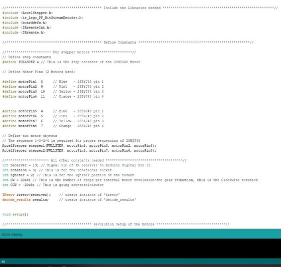
I will break my arduino code into two sections. The first section I will discuss the libraries used, constants, and initial setup. To begin with, the libraries I used are the AccelStepper.h and IRremote.h libraries. You will have to go to sketch and click manage libraries, in the search tab type IRremote and a list will pop up, choose the one by shirriff and install the latest version. Do the same for AccelStepper that is created by Mike McCauley, choose that one and install it. The reason on using the AccelStepper and not the regular Stepper library is that with AccelStepper it allows both of your stepper motors to rotate at the same time, whereas stepper only allows your motors to rotate one at a time. Now onto the constants, with the step constant you need to define a FullStep of 4, this is the step constant for the 28BYJ-48 stepper motor and depending on what motor you have the FullStep can be different. Next define the pins you used between your Arduino and the ULN2003 motorboard. After define the two motor and make sure to use 1-3-2-4 pattern, since this is the proper sequence for the 28BYJ-48 stepper motor. Next define all other constants, you need to create a constant for receiver, rotation, igniter, clockwise, counterclockwise rotation, IRrecv, and decode_results. All of these constants will be needed for the main code down below. For receiver, rotation, and igniter, the constants are the pins you use for each one. For an example if you have been using my Fritzing diagrams you will use pin 13, 3, and 2 for the constants. Under void setup you need to setup the two stepper motors. Create a max speed that the motor will run to, since we are using a 28BYJ-48 stepper motor the max speed will be 1000 rpm. Next set an acceleration that way the motor can slowly accelerate up to max speed, and finally create an initial speed that the motors will run on in my case I used 700 rpm. Now start the IR receiver by using the enable command. Configures the specified pin to behave either as an input or an output by using the pinMode command, specify rotation and igniter as an output. Make sure both of the outputs are initially off by using digitalWrite to turn them off.
Step 13: Arduino Code Part 2:
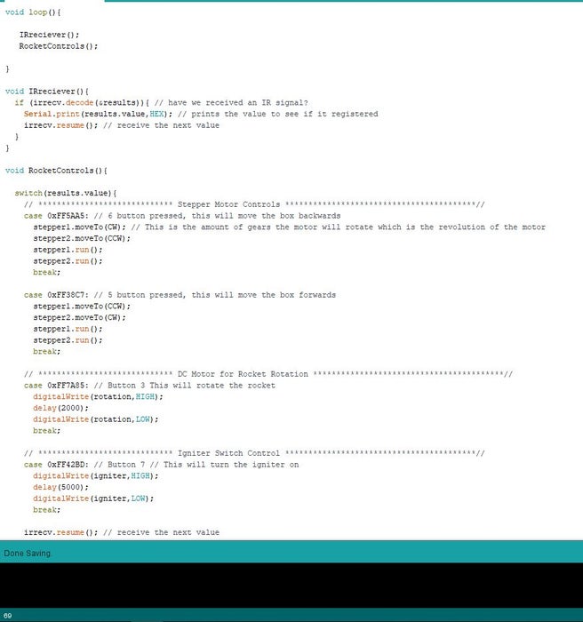
Now onto part 2. In order to clean the code out I create two separate void loops one for IRreciever and one for RocketControl. The loop for IRreciever is a check loop to make sure your IR sensor is receiving signal from your remote that you are using. The irrecv.decode command is to check to see if there is a signal, if yes proceed to the next part which is serial printing the value you are receiving from the remote in HEX form. Now onto the RocketControls. Start off by using the switch() command, this command is checking which button is pressed from your remote control. Next you will need a case structure that will specify different cases, for an example button 6 in HEX is FF5AA5 and you need to have the 0x in front in order for the case structure to work. Within the case structure write your program that you want to run, in my example I used button 6 for forwards rotation of the wheels. The moveTo() command is an AccelStepper command that moves the stepper motor to that location. The run() command executes all of the stepper1 commands. This is the same for case structure button 5. For the rotation of the DC motor, when we press button 3 we want to turn on the DC motor to rotate the rocket by 2 seconds and then turn off which is what the program under case structure button 3 do. Lastly is the igniter program, initial we set it to be off and now we want to turn it on. We turn it on for 5 seconds to let the igniter burn off all of it’s flame and then turn off. Finally is the resume() command that waits to receive the next input from your remote. Also the remote that was used in this program is Car MP3 remote, different remote many have different HEX values, you can always google them to find out what they are.
Source: Rocket Launch Pad