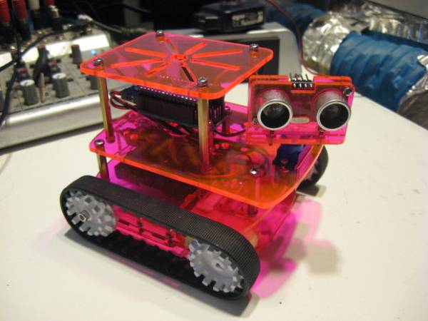
This is the assembly instructions for the Medium Tank from Rocket Brand Studios. This is a great little robot kit, and can be purchased as a complete kit or as a rolling chassis, ready for the micro controller of your choice –Arudino Uno, Duemilanove, Picaxe 28 board, or Gadget Gangster Propeller Board. The Medium Tank comes in lots of super-duper colors (and colours!) so be sure to stop by the website to see what is available.
Step 1: Prepare
Alright there, Skippy –Unwrap everything and get ready to get going.
You will need:
- Little screwdrivers
- X-acto knife
- Soldering iron and small solder
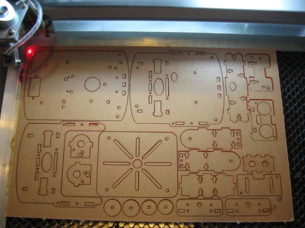
Now, lets go ahead and talk about the elephant in the room… The laser-cut acrylic has a distinctive smell. The good news is that most of that funky goodness is in the paper backing of the plexi and not the actual plexiglass. Unwrap all the pieces by peeling off the paper plastic and get it out of the house. The smell will go with it, I promise.
Step 2: Assembly 1
- Start by soldering a capacitor and one red/black wire to your motor (see photo)
- Attaching the 2 motor mounts to the motors themselves with (2) 2-56 x 1″ screws and nuts.
- Place the motor’s cross member between the 2 motor mounts and place this assembly on the bottom plate
- Secure this assembly with (2) 2-56 x 3/8″ screws and nuts
Step 3: Assembly 2
- Attach the 2 rear wheel supports to the rear cross member (note: this is similar to the motors, but includes a screw coming in from the side –see pictures)
- Place this assembly on the bottom plate
- Attach this assembly to the bottom plate with (6) 2-56 x 3/8 screws through the bottom plate
Step 4: Assembly 3
- Find the top plate and note that the hole for the battery wires must be on the left (I’m pointing to it in the picture)
- Install the (4) 20mm standoffs
- Route the motor wires through the center hole and place the top plate over the bottom assembly
- Wiggle it around a bit and get all the “tabs” to fit in their corresponding “sockets” and also get the motors to sit in their little cut-outs
- Screw the top plate down with (8) 2-56 x 3/8 screws. It is handy to use some needle-nose pliers to get the (4) “center” nuts up-and-in-there.
Step 5:
- Find the electronics plate, your servo
- If you purchased a complete kit with an Arduino Nano and Undershield, install the (3) 10mm stand-offs. These should be installed with nuts on the underside of the plexiglass plate and the end with screws, going up.
- If you are using a different brain (not the Nano) you will need to place your micro controller board on top of the plate and find the mounting holes that line up. If you are using stand-offs or spacers that will need to be attached via the underside of the plate, attach them now.
- Install the servo with the shaft positioned so it is centered and screw it down with (2) 2-56 x 3/8 screws. Route the wire through the center hole
- Prepare your switch plate. Install the 2 switches (if you want to switch the data power and motor power individually) and solder a short piece of wire between them.
- Prepare the battery pack. Find the (2) 2-pin leads and connect the 2 black wires to the black wire coming out of the battery pack –solder it and tape or shrink tube it. The red wire from the battery pack and the (2) red wires from the leads will be left disconnected for now, until we install the battery holder.
- Install the battery pack to the underside of the top deck (not the electronics deck) using the (2) 2-56 x 1/4″ flat-head screws (they are the black ones)
- Run the battery pack wires up through the hole in the deck
- Place the switch plate’s tabs into the 3 socket holes toward the back of the plate
- Finish up your soldering. The red wire from the battery gets soldered to the first switch and also to the jumper going to the second switch. (This will send power to both switches)
- Solder the last 2 red wires (from the 2-pin leads) to the 2 switches. (This will send power to the micro controller and motors as each switch is clicked)
- Place the electronics plate (running all the wires through the center hole) on the bottom assembly and attach it to the stand-offs
Step 6: Assembly 5
- Unwrap your tracks set being careful not to loose the little washers
- Press the 2 front wheels on to the motor shafts. They should not go on all the way, leave a 1/8″ or so. Also, the “teeth” of the wheel should point to the outside
- Grab a rear wheel (with a round center hole) and slide the axle bolt through it. Now add, in this order, a washer, the small circle and then the bigger circle. Now slide the bolt/wheel assembly through the hole in the back of the rear wheel support. Attach it with the nut.
- Repeat all this for the other side.
- You may now (carefully) stretch your tracks on
For more detail: Rocket Brand Studios Medium Tank